Crusher

The technology of a pulverizer and a fulcrum shaft is applied in the direction of grain processing, etc., which can solve the problems of difficult cleaning operations and time-consuming, and achieve the effect of simple structure and reduced manufacturing cost.

Inactive Publication Date: 2011-10-26
MATSUI MFG
View PDF1 Cites 1 Cited by
  • Summary
  • Abstract
  • Description
  • Claims
  • Application Information

AI Technical Summary

Benefits of technology

The invention relates to an improved mechanism for cutting materials such as paper or plastic material that has been cut into smaller pieces. This makes it easier than traditional methods like saw blades because there're no moving parts involved during use. By making certain movements about one part instead of all at once, this reduces costs associated with machining these small components. Additionally, when multiple tools work together simultaneously, they only require one type of tool while other types may also have their own advantages over each others.

Problems solved by technology

This patented technical problem addressed in this patents relates to improving the efficiency and effectiveness of removing scrapes from various types of reservoirs containing polymers made up mainly of unsaturated carboxylate groups. Current methods involve collecting them manually through an opening near where they may fall out onto ground level after being dumped away. These manual processes take longer than desired due to the complexity involved in maintaining proper alignment within the device itself.

Method used


Image

  • Crusher
  • Crusher
  • Crusher

Examples


Embodiment approach 1

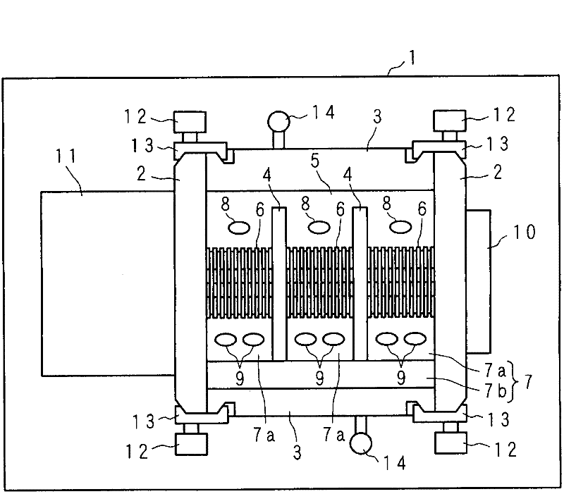
[0051] Hereinafter, this invention is demonstrated based on drawing which shows this embodiment. figure 1 It is a schematic diagram of main parts seen from the top of the pulverizer of the present invention. In the drawings, 1 is a metal support base with an open center. On the upper surface of the support platform 1, a pair of metal fixed side walls 2, 2 at an appropriate distance are oppositely arranged, on both sides of the fixed side walls 2, 2, to be clamped by the fixed side walls 2, 2 A pair of swing side walls 3, 3 made of metal are arranged in a holding manner, and the housing is composed of the fixed side walls 2, 2 and the swing side walls 3, 3. In addition, each fixed side wall 2 is fixed to the supporting table 1 with bolts.

[0052] A bearing 10 is mounted on approximately the central portion of one fixed side wall 2, and a motor 11 having a speed reducer is mounted on the other fixed side wall 2, and a rotating shaft (not shown) interlocked with the motor shaft o

Embodiment approach 2

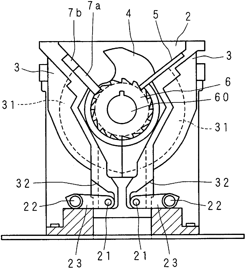
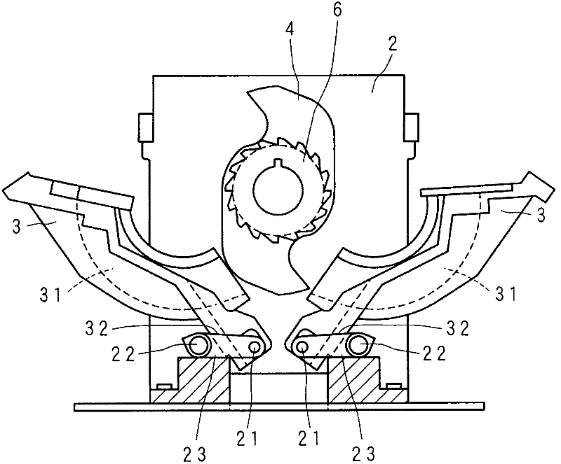
[0087] Figure 7 It is a schematic diagram of main parts seen from the front of the pulverizer of Embodiment 2. The difference from Embodiment 1 is that bolts are used instead of through shafts passing through between the fixed side walls 2 , 2 . Such as Figure 7 As shown, instead of straddling and fixing between the fixed side walls 2 and 2 , bolts 24 serving as second fulcrum axes are respectively provided on each fixed side wall 2 . That is, bolts 24 are respectively provided on the two fixed side walls 2 , 2 . The fixed side wall 2 is provided with a through hole 22c for passing a bolt 24, and a nut 22a is screwed to the bolt 24 passed through the through hole 22c and the hole 23b (another hole) of the interlocking plate 23. The bolt 24 installed in the hole 23b of the interlocking plate 23 provided between the swing side wall 3 and the fixed side wall 2 passes through the through hole 22c of the fixed side wall 2 and is screwed with the nut 22a. Accordingly, compared wi


PUM


Abstract

The present invention provides a crusher which can be manufactured at reduced cost and can be cleaned easily. Interlock plates (23, 23) which are support members are arranged at positions below a rotating shaft (60) and between each of fixed side walls (2) and two rocking side walls (3, 3). Two holes are formed in each of the interlock plates (23) so as to be spaced from each other an appropriate distance, a pin (21) functioning as a first fulcrum shaft is inserted and mounted in one of the holes, and a through-shaft (22) functioning as a second fulcrum shaft is mounted in the other hole. The pin (21) is provided to a side surface of each rocking side wall (3), the side surface facing the associated one of the two fixed side walls (2) each provided on one side of the rocking side wall (3). That is, the four pins (21) are individually provided so as to correspond to the four interlock plates (23).

Description


Claims


Application Information

Patent Timeline
Owner MATSUI MFG
Why Eureka
Try Eureka