Contact dynamic sealing method and disc sealing ring dynamic sealing device

A sealing ring and dynamic sealing technology, applied in the direction of engine sealing, transmission box, engine components, etc., can solve the problems of sealing ring leakage, bearing and shaft wear, etc., and achieve the effects of long service life, convenient installation and disassembly, and simple structure

Inactive Publication Date: 2011-12-14
鞍山重型矿山机器股份有限公司
View PDF6 Cites 11 Cited by
  • Summary
  • Abstract
  • Description
  • Claims
  • Application Information

AI Technical Summary

Problems solved by technology

[0003] The purpose of the present invention is to provide a contact dynamic sealing meth

Method used


Image

  • Contact dynamic sealing method and disc sealing ring dynamic sealing device
  • Contact dynamic sealing method and disc sealing ring dynamic sealing device
  • Contact dynamic sealing method and disc sealing ring dynamic sealing device

Examples


Embodiment Construction

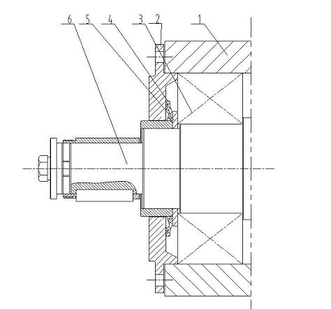
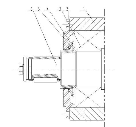
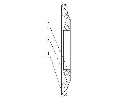
[0013] The contact dynamic sealing method is: near the leakage gap of the transmission device, there is a dish-shaped sealing ring composed of a positioning ring, an elastomer and a sealing ring, and the positioning ring of the sealing ring is installed on the journal of the transmission shaft or box. The inner side of the body bearing sealing gland, so that the sealing ring of the sealing ring is in close contact with the inner surface of the bearing sealing gland or the side of the bearing retaining ring, blocking the leakage gap between the transmission shaft and the box bearing sealing gland, realizing the Transmission seals.

[0014] The embodiment of the present invention will be described below in conjunction with the accompanying drawings, which mainly consists of a transmission case 1, a bearing sealing gland 2, a bearing 3 and a drive shaft 6. A bearing retaining ring 5 is installed on the journal of the transmission shaft 6, and a disc sealing ring 4 is installed betwe


PUM


Abstract

A contact type dynamic sealing method and a disc-shaped sealing ring dynamic sealing device belong to the dynamic sealing device in the field of mechanical transmission. It solves the problem of oil leakage caused by the wear and aging of the traditional cup sealing ring. Near the leakage gap of the transmission device, there is a dish-shaped sealing ring composed of a positioning ring, an elastic body and at least one sealing ring. Install the positioning ring of the sealing ring on the journal of the transmission shaft or the sealing pressure of the box bearing. The inner side of the cover, so that the sealing ring of the sealing ring is in close contact with the inner surface of the bearing sealing gland or the side of the bearing retaining ring, blocking the leakage gap between the transmission shaft and the box bearing sealing gland to achieve the purpose of sealing. There are many structural forms of the disc seal ring, which has the characteristics of simple structure, convenient installation and disassembly, good sealing effect and long service life. It is suitable for dustproof and lubricating oil sealing of various transmission boxes.

Description


Claims


Application Information

Patent Timeline
Owner 鞍山重型矿山机器股份有限公司
Why Eureka
Try Eureka