Improved flat-panel type photovoltaic transducer

A transducer and flat-plate technology, which is applied in the field of improved solar concentrators, can solve the problem of high threshold and achieve the effects of cost reduction and convenient use

Inactive Publication Date: 2012-01-11
郭保光
View PDF3 Cites 0 Cited by
  • Summary
  • Abstract
  • Description
  • Claims
  • Application Information

AI Technical Summary

Problems solved by technology

For medium and small-scale solar power generation

Method used


Image

  • Improved flat-panel type photovoltaic transducer
  • Improved flat-panel type photovoltaic transducer
  • Improved flat-panel type photovoltaic transducer

Examples


Embodiment Construction

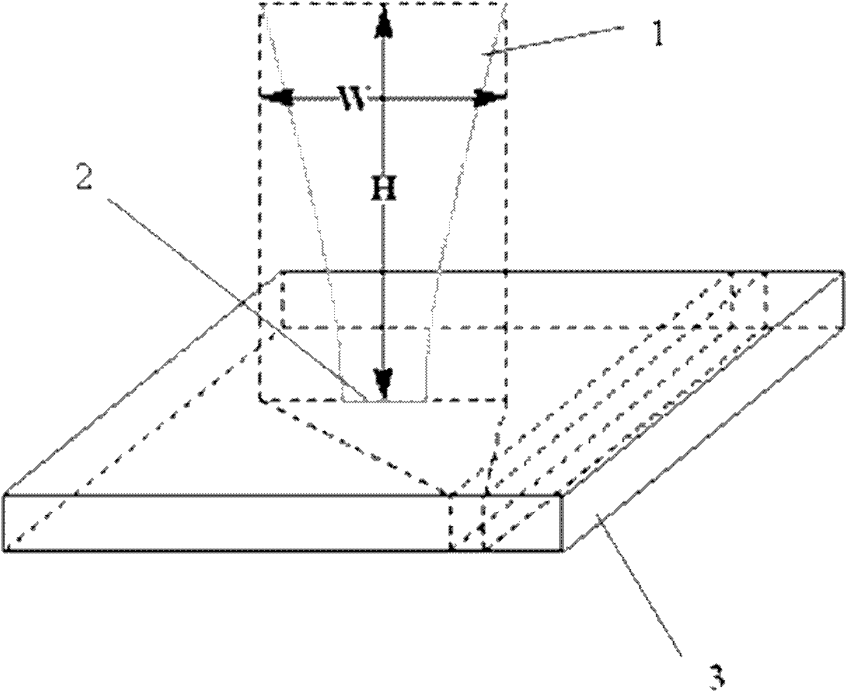
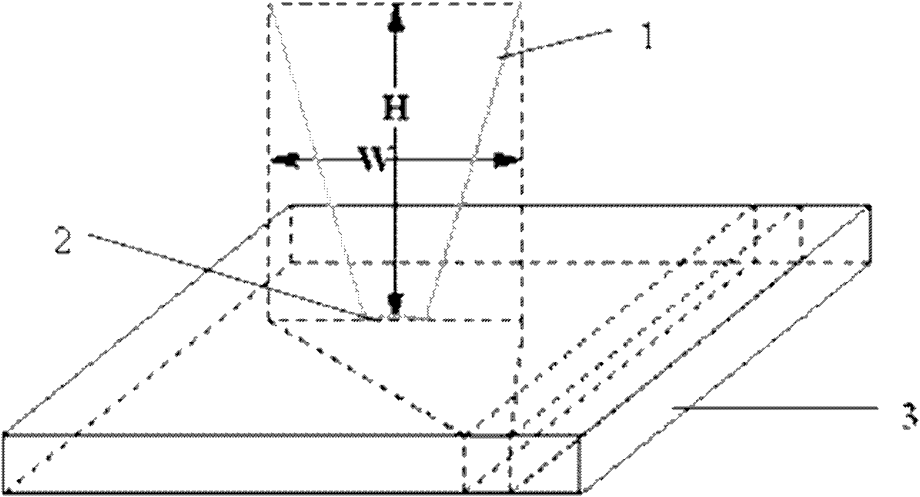
[0042] As shown in Figure 1. In order to illustrate the shape of the reflective groove formed by the reflective film, the cross section of the reflective groove is a trumpet shape with a large mouth and a small bottom. It may be advisable to think of the flat-shaped finished product as composed of strip-shaped units (the reflective grooves are installed parallel to the east-west direction). The reflective film of each unit is made into a groove shape, and its cross-section is shown in Figure 1 ( Figure 1a , b) shown, there are two styles. The two styles have their own strengths. The cross section of the reflective film of the first style is a hyperbola. There is a plate-shaped receiver between the reflective film with a hyperbolic cross-section at the bottom of the groove. Generally speaking, the hyperbola adopts a confocal hyperbola, and the hyperbolas on both sides can adopt hyperbolas with different eccentricities. (The shape of the receiver has several changes, see below)


PUM


Abstract

The invention relates to an improved flat-panel type photovoltaic transducer. In the transducer provided by the invention, light reflection grooves are uniformly arranged on a plane to be used as daylight collectors; light absorption grooves are formed at the bottom of the light reflection grooves and used for installing photovoltaic receiving devices; the cross sections of the light reflection grooves are in a horn shape with large mouth and small bottom; the cross sections of reflecting films at the two sides of the light reflection grooves are dual curves; a flat-panel photovoltaic receiver is arranged between the dual curves at the bottom of the grooves; or the cross sections of the reflecting films at the two sides of the light reflection grooves are straight lines; the cross sections of the light reflection grooves form a trapezoid; and correspondingly, light receivers are installed at the bottom of the grooves, and the cross section shape of the light receivers is a circular arc or a straight line. When the light intensity is enhanced for three times, the conversion efficiency of the grooves can be improved for about 5-6%. The final finished product of the improved flat-panel type photovoltaic transducer is in a panel shape, is the same to a flat-panel type photovoltaic transducer and is most suitable for substituting the building material of a roof.

Description


Claims


Application Information

Patent Timeline
Owner 郭保光
Why Eureka
Try Eureka