Partial-rotating driving device used for controlling valve

A technology of rotary drive and valve control, which is applied in the direction of valve operation/release device, valve device, valve details, etc. It can solve the problems of small space in the control inner cavity, poor sealing, and affect the service life of the product, and achieve a large output speed range. , Guaranteed sealing performance and low processing cost

Inactive Publication Date: 2012-03-07
TIANJIN AIKETE MEASUREMENT CONTROL TECH
View PDF0 Cites 2 Cited by
  • Summary
  • Abstract
  • Description
  • Claims
  • Application Information

AI Technical Summary

Problems solved by technology

One is that the QB type has manual/electric switching, which is not a semi-automatic electric priority in a complete sense (the switching handle must be pushed and held during operation), which causes inconvenience in manual operation and it is not suitable to use the hand wheel; its control cavity is small; the whole machine Poor protection performance, can only reach IP54, poor sealing and other technical problems
The other is that the QT type has a built-in motor, which limits the output torque. Long-term operation

Method used


Image

  • Partial-rotating driving device used for controlling valve
  • Partial-rotating driving device used for controlling valve
  • Partial-rotating driving device used for controlling valve

Examples


Example Embodiment

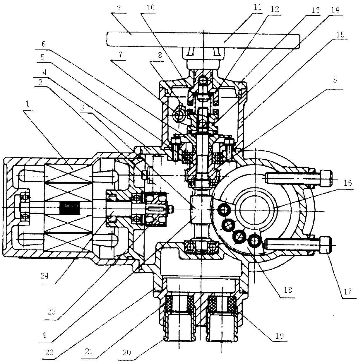
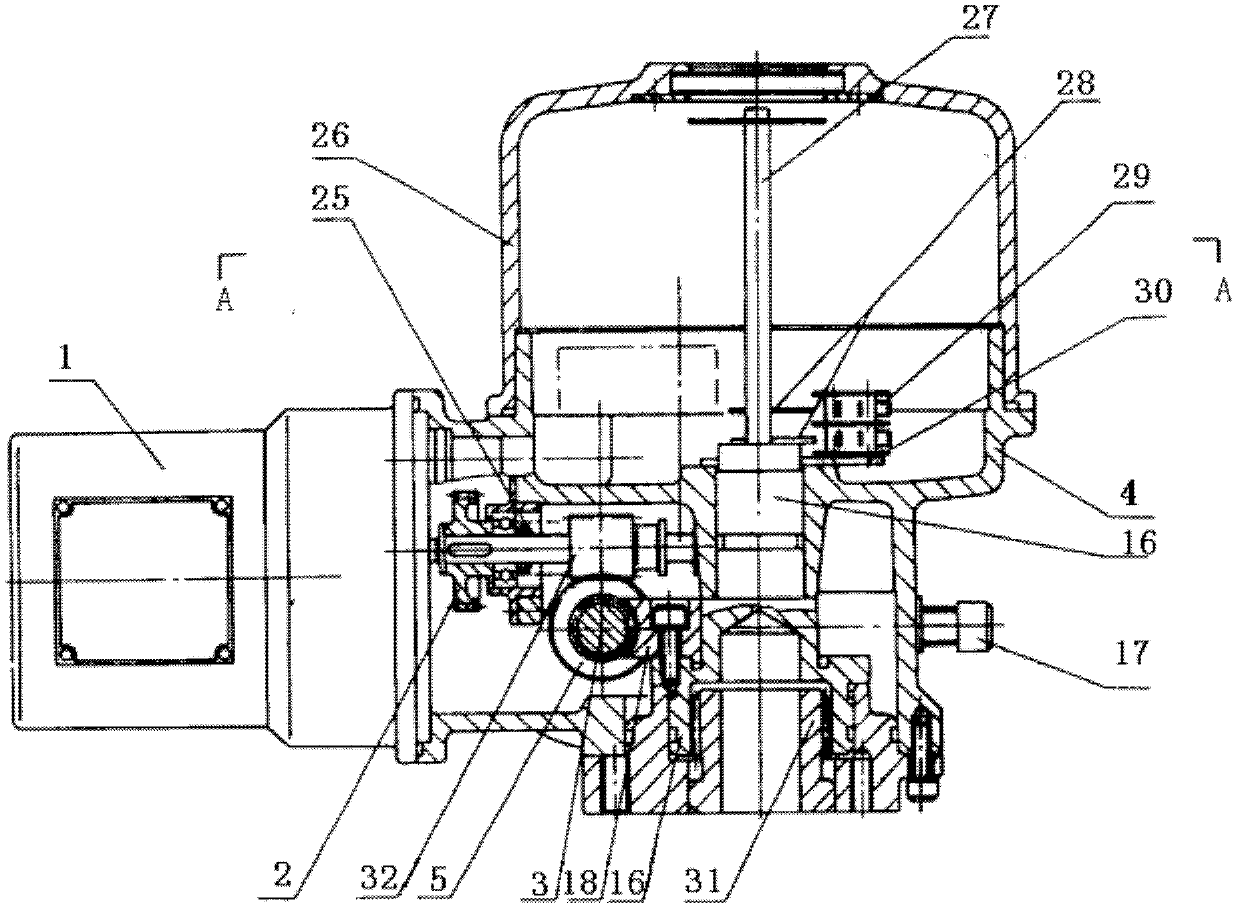
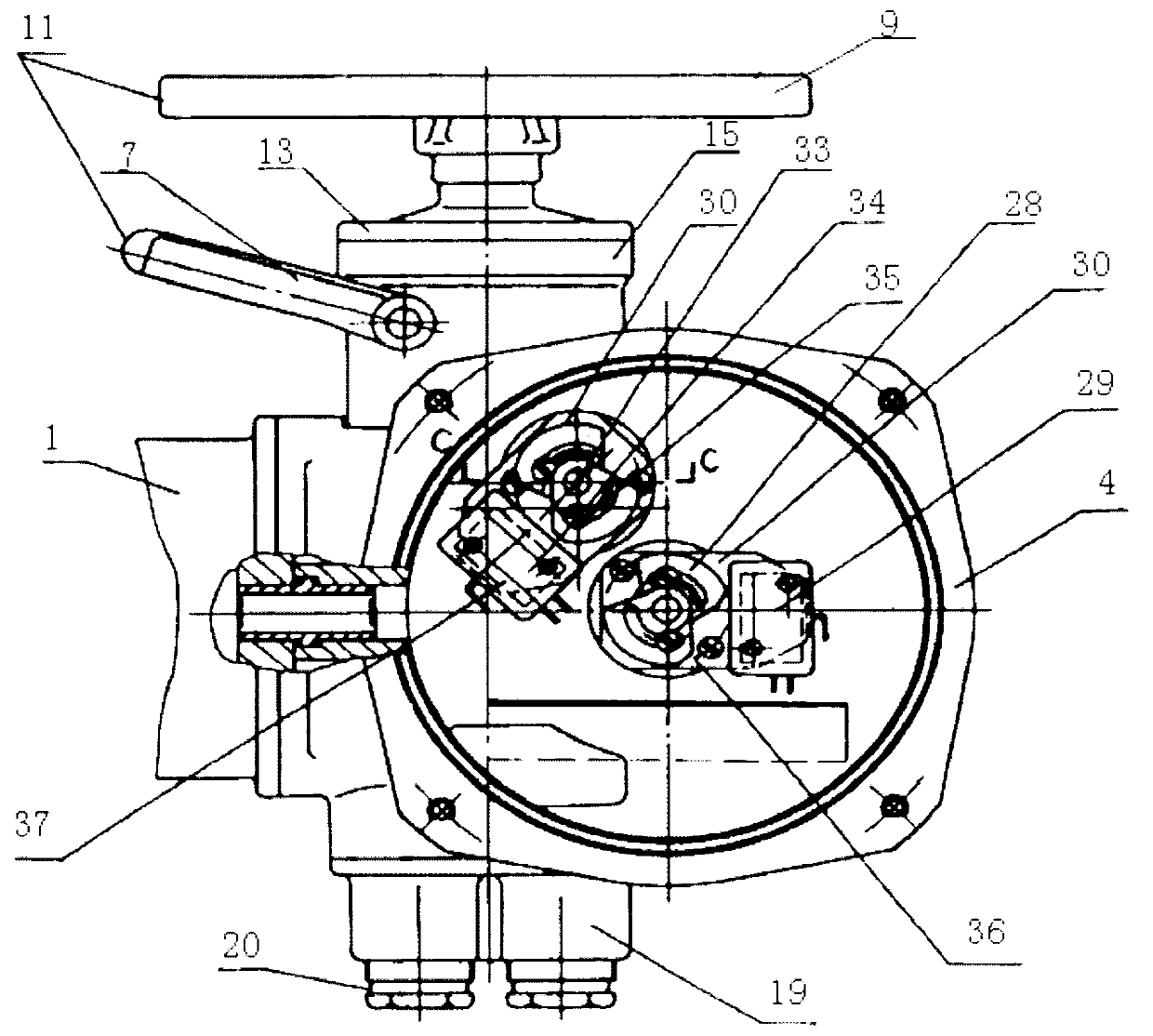
[0034] Such as figure 1 , 2 , 3, 4 and 5, the present invention is a part-turn drive device for valve control.

[0035] The structure of this embodiment: a part-turn drive device for valve control, including a motor 1, a manual mechanism 11 and a manual / electric switching mechanism 11, a deceleration mechanism 22, a stroke control mechanism 36, a torque control mechanism 37, and an inlet seal Mechanism, main box body 4 and output shaft 16, motor 1 is installed on the outer side of main box body 4, and the motor gear is perpendicular to the low-speed worm 3 installed in main box body 4; manual mechanism 11 includes jaws with clutch 14 during operation The matched manual shaft 12, a manual cover 13 fixed on the main box 4 and rotatably connected to the manual shaft 12, and a hand wheel 9 fixedly connected to the other end of the manual shaft 12; the hand / electric switching mechanism 11 includes The handle sleeve 40 on the main box body 4, the handle sleeve 40 is equipped with the


PUM


Abstract

The invention provides a partial-rotating driving device used for controlling a valve. The partial-rotating driving device is characterized by comprising a motor, a manual mechanism, a manual/motor-driven switch mechanism, a retarding mechanism, a stroke control mechanism, a torque controlling mechanism, an incoming line sealing mechanism, a main box body and an output shaft, the motor is installed on the outer side of the main box body, a manual/motor-driven switch mechanism comprises a handle sleeve fastened on the main box body, the handle sleeve is provided with a switch handle shaft, a shifting fork on the switch handle shaft is provided with an upright post, a separator disk and a high-speed worm. The retarding mechanism is a combination of a one-stage gear pair and a two-stage worm gear pair; the incoming line sealing mechanism is arranged at the lower side of the main box body. The invention has the advantageous effects that semi-automatic electric precedence is realized by the mechanism, the sealing property of product electrical wiring is ensured through the arrangement of the incoming line sealing mechanism; since the motor is arranged outside, the volume of the control cavity of the main box body is enlarged so that support subservience control elements can be arranged conveniently; and ideal product ratio range is achieved due to the arrangement of the retarding mechanism, thereby obtaining larger output rotation speed range.

Description


Claims


Application Information

Patent Timeline
Owner TIANJIN AIKETE MEASUREMENT CONTROL TECH
Why Eureka
Try Eureka