Pipe coiling machine and engineering machine with pipe coiling machine

A technology of engineering machinery and hose reels, which is applied in earth movers/excavators, construction, etc., can solve the problems of high processing cost and assembly cost, increase system instability factors, and increase maintenance cost of seals, etc., to achieve Effects of enhancing stability, reducing cost, and simplifying system structure

Inactive Publication Date: 2012-07-25
BEIJING SANY HEAVY MASCH CO LTD
View PDF5 Cites 0 Cited by
  • Summary
  • Abstract
  • Description
  • Claims
  • Application Information

AI Technical Summary

Benefits of technology

This patented technology allows for direct connection between an electric motor (power source) on one end or another side of its tube reels while still allowing it to be rotated freely by driving them through this process. It does away with any extra parts like bearings that are needed when turning off these motors. Additionally, the weight of the disc makes it easier than traditional methods because they don't require more space around their own wheeled hubs.

Problems solved by technology

This patented describes different types of mechanical systems called Hydranes Reels (HRS) which can hold water-based fluids like gasoline during operation. These mechanisms have several technical problem addressed at this patents including costly manufacturing processes, complexity of design, increased risk of failure due to factors like vibrations caused by pump impellers, and potential issues related to maintaining proper performance over an extended period of usage.

Method used


Image

  • Pipe coiling machine and engineering machine with pipe coiling machine
  • Pipe coiling machine and engineering machine with pipe coiling machine
  • Pipe coiling machine and engineering machine with pipe coiling machine

Examples


Embodiment 1

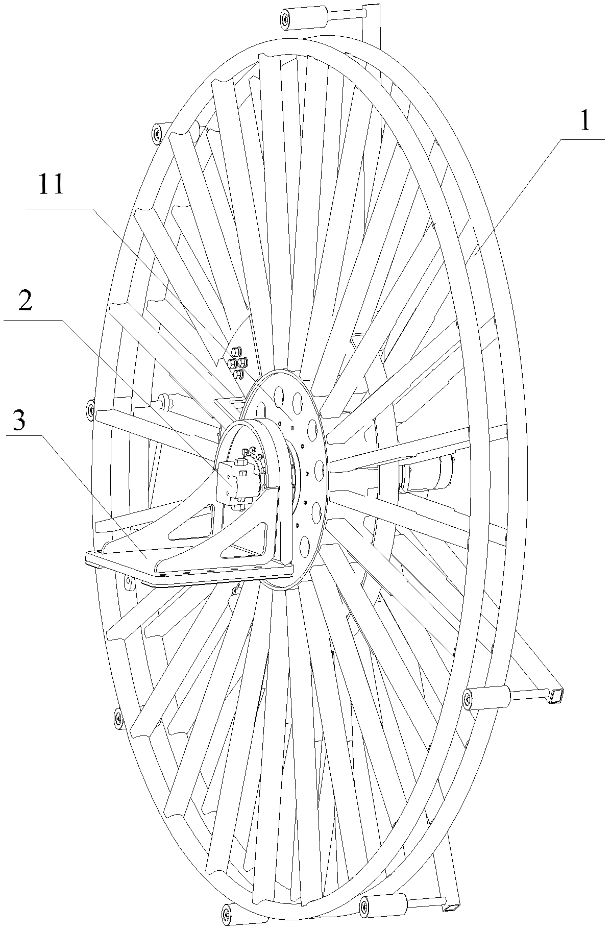
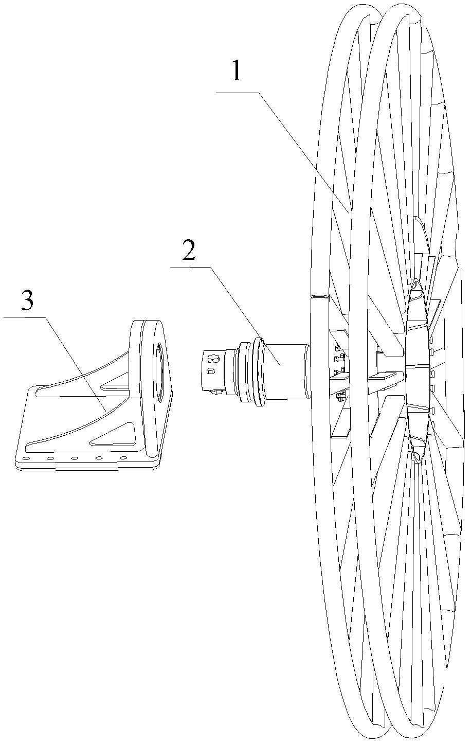
[0029] see figure 1 , figure 2 , figure 1 It is a perspective view of an embodiment of the hose reel of the present invention, figure 2 It is an exploded view of the embodiment of the hose reel of the present invention.

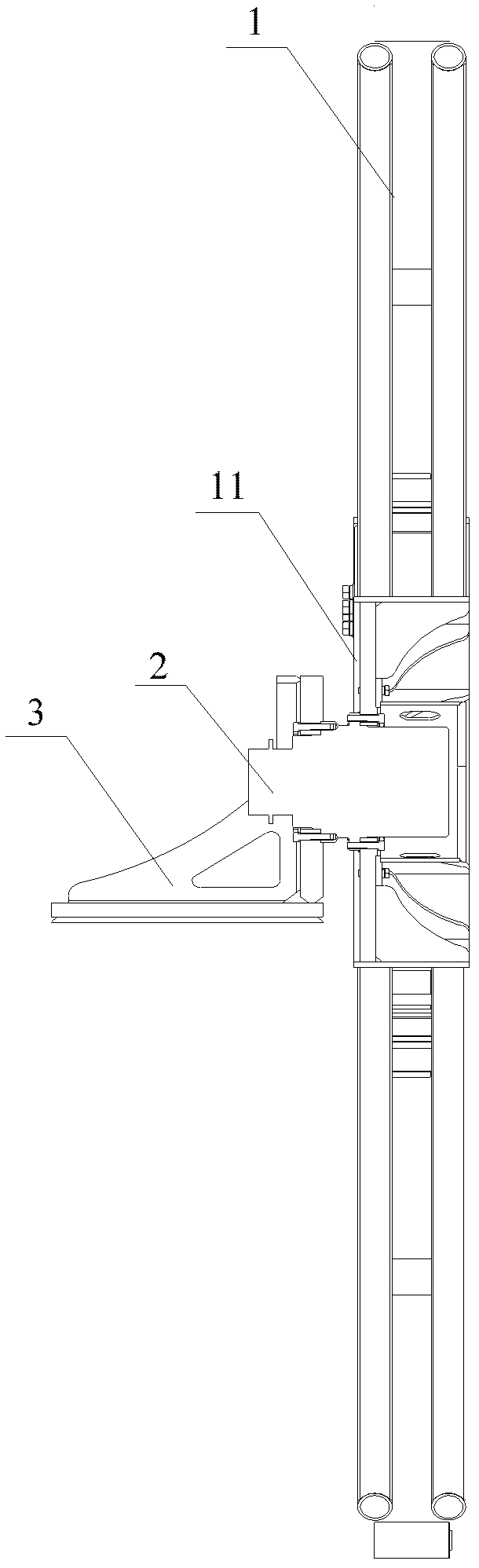
[0030] As shown in the figure, this embodiment of the hose reel includes a mounting base 3 , a power device 2 and a reel 1 . Wherein, the power device 2 is installed on the mounting seat 3, and the output flange of the power device 2 is connected with the reel flange 11 of the reel 1 to drive the reel 1 to rotate. At the same time, the power device 2 can bear a relatively large radial force, and is used to support the reel 1 and bear the gravity of the reel 1 without additional radial support system.

[0031] Preferably, the power unit 2 is a travel reducer, and its structure is as follows Figure 4 As shown, it includes a first mounting flange 21A and a first output flange 22A, the first mounting flange 21A is connected to the mounting seat 3, and the fi

Embodiment 2

[0039] see Figure 7 , Figure 8 , Figure 7 It is a structural schematic diagram of the wheel motor of the present invention; Figure 8 It is an axial sectional view of another embodiment of the hose reel of the present invention.

[0040] As shown in the figure, this embodiment includes a mount 3 , a power unit 2 and a reel 1 . Wherein, the power device 2 is installed on the mounting seat 3, and the output flange of the power device 2 is connected with the reel flange 11 of the reel 1 to drive the reel 1 to rotate. At the same time, the power device 2 can bear a relatively large radial force, and is used to support the reel 1 and bear the gravity of the reel 1 without additional radial support system.

[0041] The power unit 2 in this embodiment is a wheel motor. The structure of the wheel motor see Figure 7 , including a second mounting flange 21B and a second output flange 22B. The second mounting flange 21B is connected with the mounting seat 3 through bolts. A reel

Embodiment 3

[0047] The present invention also proposes a construction machine, which has the hose reel described in any one of the above items.

[0048] Preferably, the construction machine is a diaphragm wall grab groover, and the hose reel controls the hydraulic hose in the diaphragm wall grab groover to retract freely.


PUM


Abstract

The invention provides a pipe coiling machine and an engineering machine with the pipe coiling machine. The pipe coiling machine comprises a mounting seat, a power device and coiling tray, wherein the power device is arranged on the mounting seat and comprises an output flange, and a coiling tray flange is fixed at the rotary center of the coiling tray; and the output flange is connected with the coiling tray flange and is used for supporting the coiling tray and driving the coiling tray to rotate. The power device in the pipe coiling device is directly connected with the coiling tray and drives the coiling tray to rotate, and other transmission mechanisms do not need to be arranged additionally. Simultaneously, the power device also can bear large radial force, a bearing system does not need to be arranged additionally to bear the gravity of the coiling tray, so that the system structure is simplified, the cost is lowered, and the stability of the system is enhanced.

Description


Claims


Application Information

Patent Timeline
Owner BEIJING SANY HEAVY MASCH CO LTD
Why Eureka
Try Eureka