Ultraviolet light communication method and ultraviolet light communication system
A communication method and ultraviolet light technology, applied in the field of ultraviolet light communication method and ultraviolet light communication system, can solve the problems of high price, short service life, difficult low-voltage high-speed drive, etc., achieve low price, long service life, and realize communication ability Effect
- Summary
- Abstract
- Description
- Claims
- Application Information
AI Technical Summary
Benefits of technology
Problems solved by technology
Method used
Image

Examples
Embodiment 1
[0040] For the ultraviolet light communication system, the selection of the light source is very important. Generally, it is required that the emission spectrum of the light source must cover the sun-blind area, and there must be sufficient emission power, and the spectrum of the non-sun-blind ultraviolet area should be minimized as much as possible. The implementation of the present invention For example, the ultraviolet germicidal lamp is used as the carrier of the modulation signal to spread the light signal.
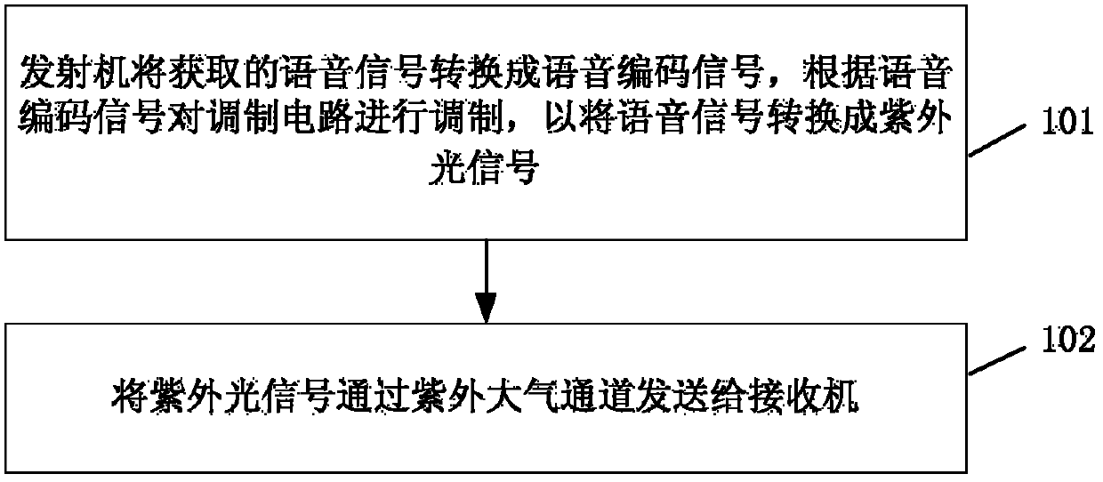
[0041] see figure 1 , an embodiment of the present invention provides an ultraviolet light communication method, the method comprising:
[0042] Step 101: The transmitter converts the acquired voice signal into a voice coded signal, and modulates the modulation circuit according to the voice coded signal, so as to convert the voice signal into an ultraviolet light signal;
[0043] Step 102: Send the ultraviolet light signal to the receiver through the ultraviolet atmos
Embodiment 2
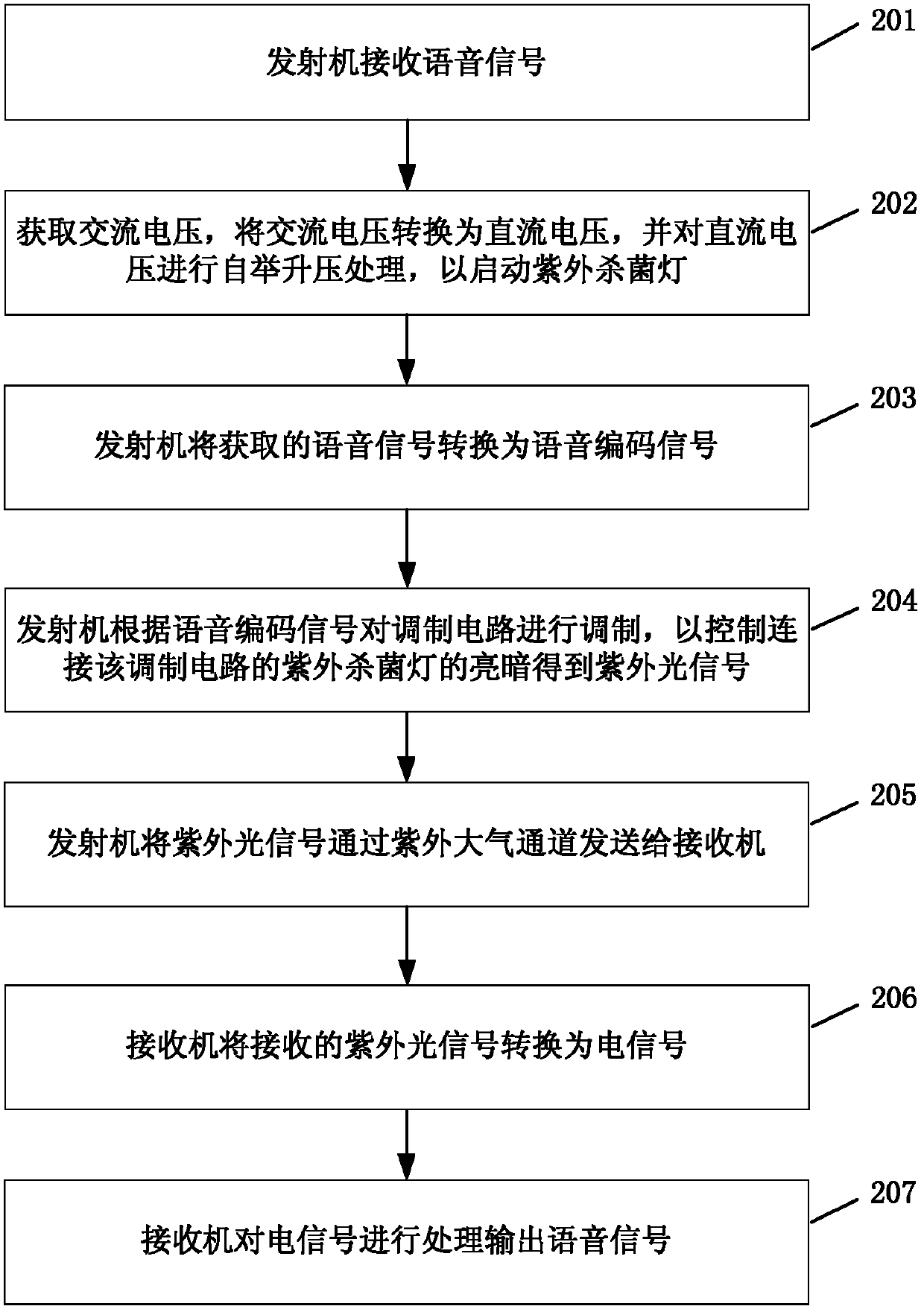
[0046] see figure 2 , an embodiment of the present invention provides an ultraviolet light communication method, the method comprising:
[0047] Step 201: the transmitter receives a voice signal;
[0048] Wherein, the transmitter receives the voice signal, and converts the voice signal into an optical signal through the processing of the transmitter, and transmits the optical signal.
[0049] Step 202: Obtain an AC voltage, convert the AC voltage into a DC voltage, and boost the DC voltage to start the ultraviolet germicidal lamp;
[0050] Preferably, in this embodiment, obtaining a 220V AC voltage to start the ultraviolet germicidal lamp includes: converting the 220V AC voltage into a 310V DC voltage through a bridge rectifier circuit, and further converting the 310V DC voltage into an ultraviolet germicidal lamp through a booster circuit. The starting voltage of the germicidal lamp, such as the starting voltage of the ultraviolet germicidal lamp is 400V, the voltage of 310V
Embodiment 3
[0076] see Figure 4 , an embodiment of the present invention provides an ultraviolet light communication system, the system includes a transmitter 301 and a receiver 302,
[0077] The transmitter 301 is used to convert the acquired voice signal into a voice coded signal, modulate the modulation circuit according to the voice coded signal to convert the voice signal into an ultraviolet light signal, and send the ultraviolet light signal to the receiver through the ultraviolet atmospheric channel 302;
[0078] The receiver 302 receives the ultraviolet light signal, converts the ultraviolet light signal into an electrical signal, and processes the electrical signal to output a voice signal.
[0079] Among them, see Figure 5 , the transmitter 301 includes a startup module 3011, a conversion module 3012, a control module 3013 and a transmission module 3014;
[0080] The starting module 3011 is used to convert the acquired AC voltage into a DC voltage, and boost the DC voltage to
PUM
 Abstract
Description
Claims
Application Information
 - R&D Engineer
- R&D Manager
- IP Professional
- Industry Leading Data Capabilities
- Powerful AI technology
- Patent DNA Extraction
Browse by: Latest US Patents, China's latest patents, Technical Efficacy Thesaurus, Application Domain, Technology Topic.
© 2024 PatSnap. All rights reserved.Legal|Privacy policy|Modern Slavery Act Transparency Statement|Sitemap