Cutting die processing device and cutting die automatic processing technology

A processing device and automatic processing technology, applied in cutting tools, household utensils, applications, etc., can solve the problems of time-consuming and affecting the machining accuracy of cutting dies, so as to save the time of manual auxiliary processing, shorten the production cycle, and increase the processing speed. Effect

Active Publication Date: 2012-10-03
深圳同致精工技术有限公司
View PDF5 Cites 2 Cited by
  • Summary
  • Abstract
  • Description
  • Claims
  • Application Information

AI Technical Summary

Benefits of technology

This new design allows for faster and more accurate cuts on both sides of a blade model without having to manually process it afterwards or requiring expensive tools like lasers. It also improves upon previous designs where only one side was able to be accurately shaped due to limitations such as lacking precision control during manufacturing processes. Overall, these improvements lead to improved efficiency and productivity while reducing costs associated therewith

Problems solved by technology

This patented describes how different types of tools like lathes or mill blades have been developed that allow for faster and easier handling during fabricating processes in order to improve their overall performance. However, current methods require both forward and backward endings from each tool separately before they can be bent properly with an electric motor driven blade.

Method used


Image

  • Cutting die processing device and cutting die automatic processing technology
  • Cutting die processing device and cutting die automatic processing technology
  • Cutting die processing device and cutting die automatic processing technology

Examples


Embodiment Construction

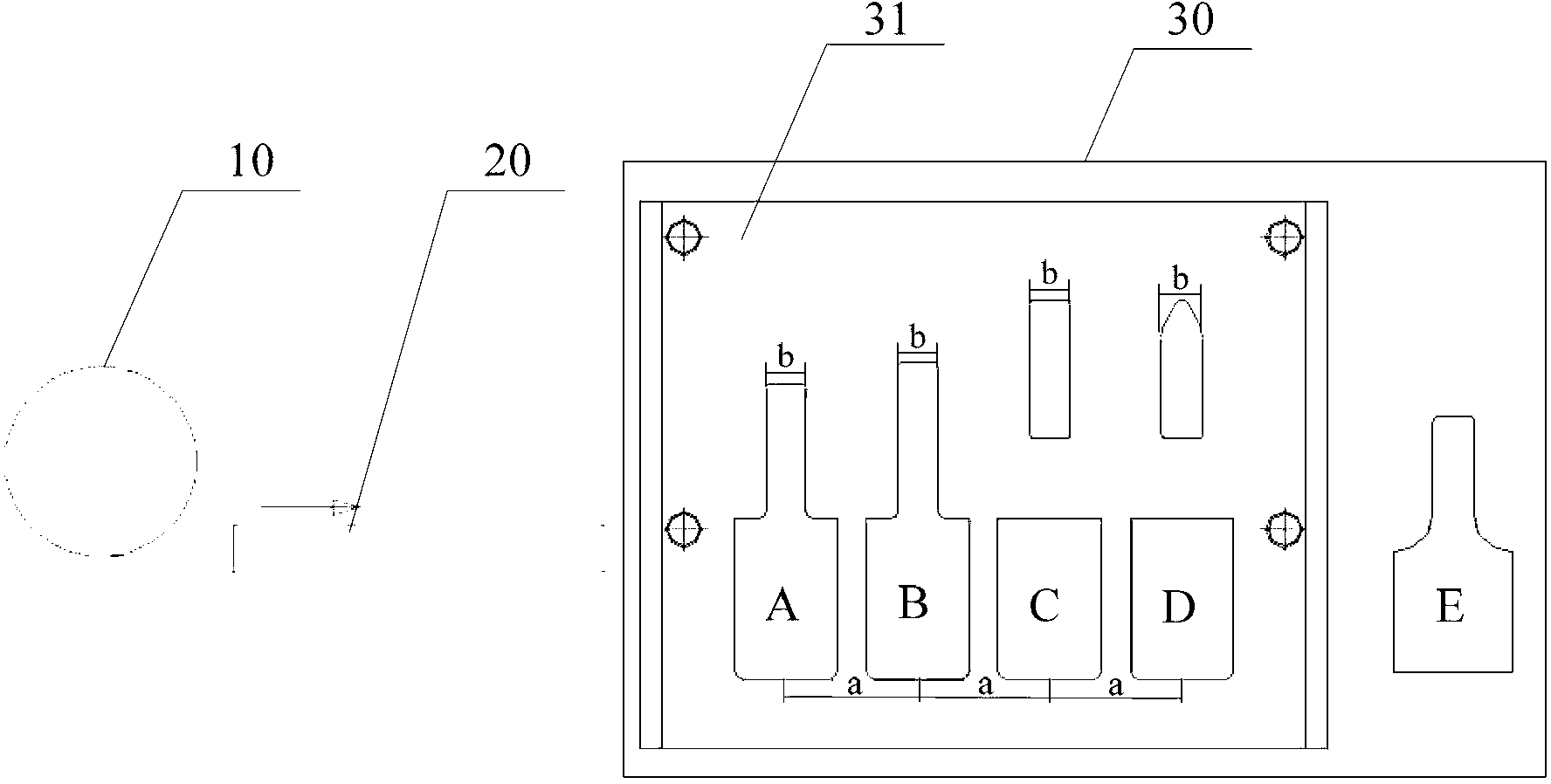
[0042] Such as figure 1 as shown, figure 1 It is a schematic structural view of the machete machine where the knife mold processing device of the preferred embodiment of the present invention is located; the machete machine includes a raw material tray 10, a feeding device 20 and a knife mold processing device 30 arranged in sequence along the conveying direction of the knife material, wherein :

[0043] The raw material tray 10 is used to provide cutting materials, and the feeding device 20 is used to provide cutting materials for the knife mold processing device 30. The knife mold processing device 30 is used to realize the flat cutting and olecranon cutting process of the front and rear ends of the knife mold.

[0044] Specifically, the knife die processing device 30 of this embodiment includes two bridge hole dies A and B, a flat cutting die C, an olecranon die D and a rear lower die E.

[0045] The two bridge hole dies A and B, as well as the flat cutting die C, the olecra


PUM


Abstract

The invention discloses a cutting die processing device and automatic processing technology. The device comprises an eagle's beak die, a bridge opening die and/or a rear end lower die. The bridge opening die is used for punching a notch of a first preset size at the front end of a die material of a feeding device. The eagle's beak die is used for punching a front end eagle's beak of the die material on the notch arranged at the front end of the die material and punched by the bridge opening die, or used for punching a notch of a second preset size at the rear end of the die material of the feeding device. The rear end lower die is used for punching a rear end eagle's beak of the die material on the notch arranged at the rear end of the die material and punched by the eagle's beak die. Thecutting die processing device overcomes the defects that the existing automatic knife bending machine can not achieve a cutting method of making eagle's beaks at the front end and the rear end of a cutting die, can save manual auxiliary machining time, greatly increases machining speed of the cutting die, and shortens a production period. Automation of devices is truly achieved, a plurality of uncertain factors caused by people are avoided, and machining precision of the cutting die is improved.

Description


Claims


Application Information

Patent Timeline
Owner 深圳同致精工技术有限公司
Why Eureka
Try Eureka