Mode locking system

A technology of clamping and clamping device, applied in the field of clamping system, can solve the problems of low production efficiency, small overall height, not enough humanization, etc., and achieve the effect of high degree of automation and high production efficiency

Inactive Publication Date: 2012-10-24
珠海市凯顺自动化科技有限公司
View PDF4 Cites 4 Cited by
  • Summary
  • Abstract
  • Description
  • Claims
  • Application Information

AI Technical Summary

Benefits of technology

This patented technology allows for efficient manufacturing by providing various features such as a horizontal working table, a tray carrying a number of stations, a movable top rod supporting two guideposts, and several other components like a screw jack assembly. These technical improvements improve the overall design and functionality of these systems while improving their stability during operation.

Problems solved by technology

This patented technical problem addressed in this patents relates to current common types of injector systems that have limitations with regards both size and productivity due to their manual operation or lacked versatility when facing different materials being processed at varying levels of pressure within certain limits.

Method used


Image

  • Mode locking system
  • Mode locking system
  • Mode locking system

Examples


Embodiment Construction

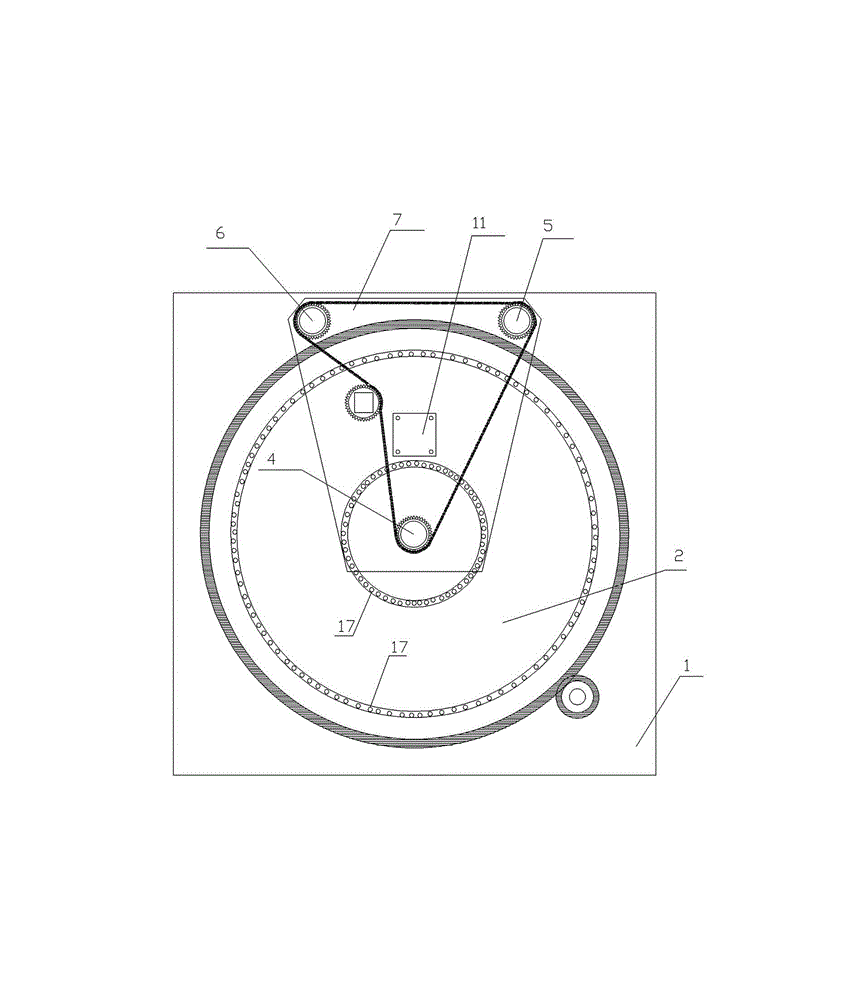
[0015] The clamping system of the present invention is compact in structure, high in automation and productivity, and reasonable in design, and is suitable for vertical injection process environments with special requirements, such as plastic magnetic injection motor rotors (integrated injection molding with extended motor shafts), various stainless steels, various Copper parts and other occasions that need to be pre-embedded. The present invention is described in further detail below in conjunction with the embodiment that accompanying drawing provides:

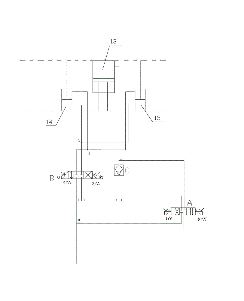
[0016] Such as figure 1 , figure 2 , image 3 As shown, the present invention includes that the mold clamping system includes a workbench 1, a turntable 2 arranged on the workbench 1, a turntable motor 3 for driving the turntable 2 to rotate, and a second wheel passing through the workbench 1. A guide post 4, a second guide post 5 and a third guide post 6, the three guide posts can be lifted up and down in the vertical dire


PUM


Abstract

The invention discloses a mode locking system with high degree of automation and high production efficiency, and capable of meeting special occasions of injection molding process. The mode locking system comprises a working table (1), a turntable (2), a turntable motor (3), a first guide pillar (4), a second guide pillar (5) and a third guide pillar (6); the three guide pillars can be vertically lift up and down; upper parts of the three guide pillars are fixed with an upper template (7); a front mould (8) is arranged on a lower part of the upper template (7); lower ends of the three guide pillars are fixed with a lower template (9); the lower template (9) is connected with a mode locking system for driving the three guide pillars for lifting movement; the turntable (2) rotates around the first guide pillar (4) as a central shaft and the is provided with at least two back molds (10) arranged symmetrically around the first column (4); and the back molds (10) and the front mold (8) are matched. The invention can be widely applied to the field of injection molding machine.

Description


Claims


Application Information

Patent Timeline
Owner 珠海市凯顺自动化科技有限公司
Why Eureka
Try Eureka