Selector circuit with fixed output state

A technology of output state and selector, which is applied in the direction of electrical components, electronic switches, pulse technology, etc., can solve the problems of signal waveform attenuation, poor driving ability, and no advantage in area, so as to achieve the effect of ensuring driving ability

Active Publication Date: 2012-10-31
INST OF ELECTRONICS CHINESE ACAD OF SCI
View PDF4 Cites 5 Cited by
  • Summary
  • Abstract
  • Description
  • Claims
  • Application Information

AI Technical Summary

Benefits of technology

This technology improves upon existing methods where multiple transistors are used together but eliminates any issues such as noise interference from neighboring devices due to electrical coupling between them. By sharing certain circuits within one device instead of individually controlled components, there're no longer an issue related to maintain proper functioning even if some parts have been changed during manufacturing process. Additionally, these techniques allow for more flexibility than previous designs because they only require specific connections on each component separately rather than all simultaneously. Overall, this innovation allows for better performance while reducing costs associated with design changes over time.

Problems solved by technology

Technological Problem: Conventional methods for controlling selectors involve adding extra components such as buffers or resistances between certain parts of the system's semiconductor integrated circuitry during operation. These techniques increase complexity and cost while reducing efficiency. Additionally, these conventional solutions require precise timing sequences and may lead to malfunctions caused by noise interference with normal operations.

Method used


Image

  • Selector circuit with fixed output state
  • Selector circuit with fixed output state
  • Selector circuit with fixed output state

Examples


Embodiment Construction

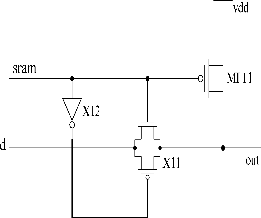
[0026] A selector circuit with a definite output state of the present invention includes the following situations:

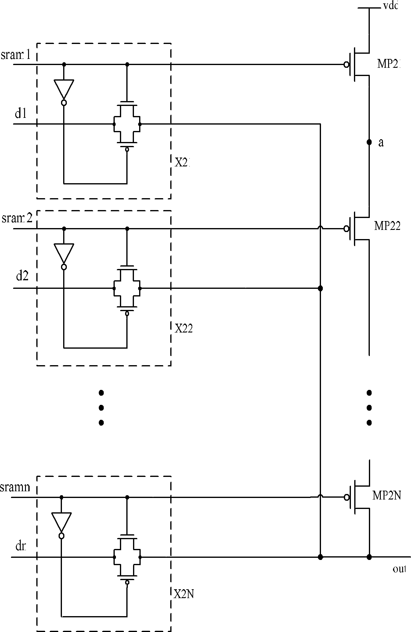
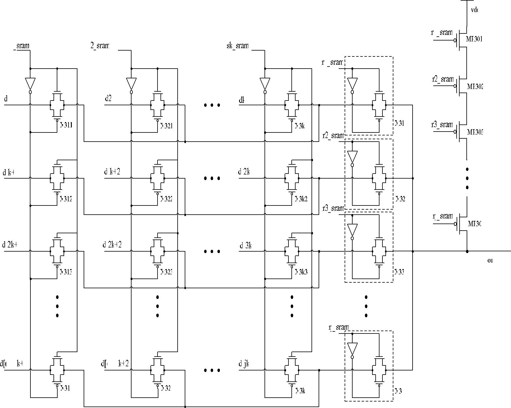
[0027] (1) One-way or multiple-way selection circuit composed of at least one transmission gate, the switch of the transmission gate is controlled by the control bit output by the control circuit and the inverter, and the value of the initial output control bit of the control circuit is zero at this time; when there is only one transmission When the gate is opened, the control circuit outputs a control bit to control the gate of the NMOS transistor of the transmission gate. The control bit is connected to the gate of the PMOS transistor that controls the output of the inverter. The input terminal of the transmission gate is connected to the data signal. Only one PMOS Pull tube, its gate is connected to the control bit, the drain is connected to the output terminal of the transmission gate, and the source is connected to the power supply terminal vdd; when n transmis


PUM


Abstract

The invention discloses a selector circuit with a fixed output state, relating to an integrated circuit technology. A selector comprises a transmission gate, a phase inerter and a PMOS (P-channel Metal Oxide Semiconductor) up-drawing tube. Control bits output by a control circuit are connected with the grid electrode of an NMOS (N-channel Metal Oxide Semiconductor) tube of the transmission gate and used for controlling the grid electrode of a PMOS tube of the transmission gate through the phase inverter, the grid electrode of the PMOS up-drawing tube is connected with the control bits, the source electrode of the PMOS up-drawing tube is connected with a power supply end vdd, and the drain electrode of the PMOS up-drawing tube is connected with the output end of the transmission gate. The circuit disclosed by the invention can be used for ensuring that the output end of the selector is not in an empty level state, but is drawn to the high level through the PMOS up-drawing tube when all output control bits are equal to zero, so that a static short-circuit current is prevented from being generated by a gate circuit connected with the output end; and the circuit disclosed by the invention is low in area overhead, low in requirement for parameters of the PMOS up-drawing tube, capable of reducing the amount of the control bits and eliminating the static short-circuit current, and little in influence to the performance of a chip.

Description


Claims


Application Information

Patent Timeline
Owner INST OF ELECTRONICS CHINESE ACAD OF SCI
Why Eureka
Try Eureka