Binary synchronization electromagnetic block brake of gantry

An electromagnetic block and brake technology, applied in drum brakes, brake types, axial brakes, etc., can solve problems such as inconvenience and brake loss gap adjustment, and achieve enhanced autonomy, improved work reliability, and reasonable force. Effect

Inactive Publication Date: 2012-11-14
SHIJIAZHUANG WULON BRAKE
View PDF0 Cites 10 Cited by
  • Summary
  • Abstract
  • Description
  • Claims
  • Application Information

AI Technical Summary

Benefits of technology

The present embodiment describes a new type of electric bicycle control device with improved efficiency and flexibility compared to traditional methods such as hydraulic systems. It uses a special mount called a fixing gearbox (GTM) instead of conventional brackets attached to it's main body. There is also no needing to adjust the position of the motors during operation due to their weight. Additionally, because they work together through a single power source, they don’t require complicated coordination designs like those found at older versions of these devices. Overall, this technology simplifies construction while maintaining high performance levels over time.

Problems solved by technology

This patented technical solution describes different types of electric magnetic blocks brazier systems commonly found on hoist machines. These solutions involve installing both double push magnets onto the driving motor's housing instead of just being able to support these components individually. Additionally, they require separate manufacturing processes due to their unique characteristics such as size differences and lack of universal compatibility. Therefore, current designs may result in unsafe situations where multiple parts can break down unexpectedly during operation.

Method used


Image

  • Binary synchronization electromagnetic block brake of gantry
  • Binary synchronization electromagnetic block brake of gantry
  • Binary synchronization electromagnetic block brake of gantry

Examples


Embodiment 1

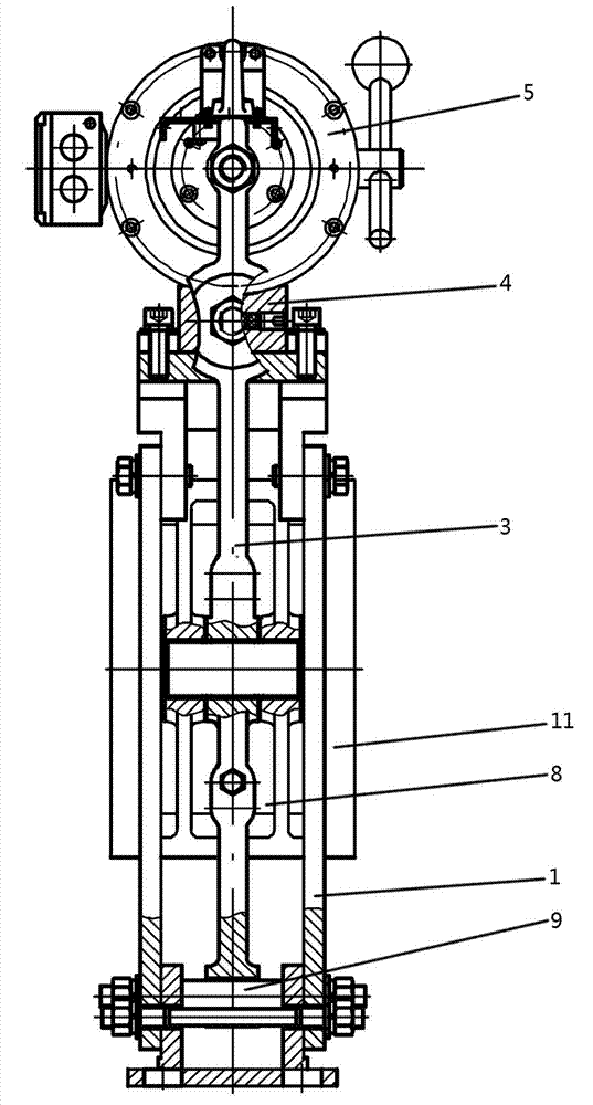
[0028] Such as figure 1 , figure 2 As shown, the gantry support 1 is a rectangular frame structure fixedly connected by a side frame, a top beam and a base. The two side frames are composed of two long strip-shaped vertical panels facing each other ( figure 2 ), the lower ends of the two vertical plates are fixedly connected to the base by bolts, and the upper ends of the two vertical plates are fixedly connected to the top beam by bolts.

[0029] A brake arm 3 is respectively connected to both sides of the gantry support 1 . The brake arm 3 is located between the two long vertical plates of the side frame, and the hinge shaft 9 passes through the two vertical plates of the side frame and the lower end of the brake arm 3 to realize the connection between the brake arm 3 and the gantry bracket 1. (Of course, the brake arm 3 can also be hinged on the base of the gantry support 1). The middle part of the brake arm 3 is connected with the inward brake shoe 8 in a conventional m

Embodiment 2

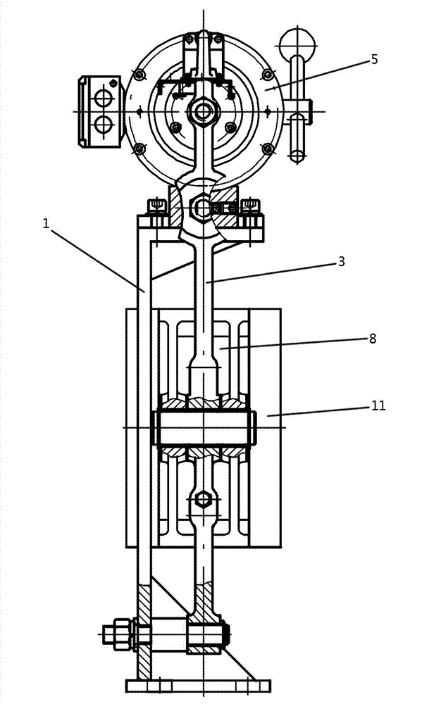
[0038] Such as figure 1 , image 3As shown, the basic structure of the present embodiment is the same as that of Embodiment 1, that is, the gantry support 1 is a rectangular frame fixedly connected by the side frame, the top beam and the base, and the double push electromagnet 5 is fixed on the top beam of the gantry support 1 , brake arms 3 are respectively hinged on both sides of the gantry bracket 1, and brake shoes 8 are connected to the brake arms 3. The concave arc surfaces of the two brake shoes 8 are opposite to the outer circle of the brake wheel 11. A pull rod 7 is connected to the upper end of each brake arm 3, and a brake spring 2 is sleeved on the pull rod 7. The gap adjusting mechanism is an adjusting screw 10 threadedly connected with a transverse screw hole on the brake arm 3 , and is locked on the brake arm 3 by a lock nut 6 .

[0039] The main difference of this embodiment is that a gantry support structure supported by a single plate surface is adopted, that

Embodiment 3

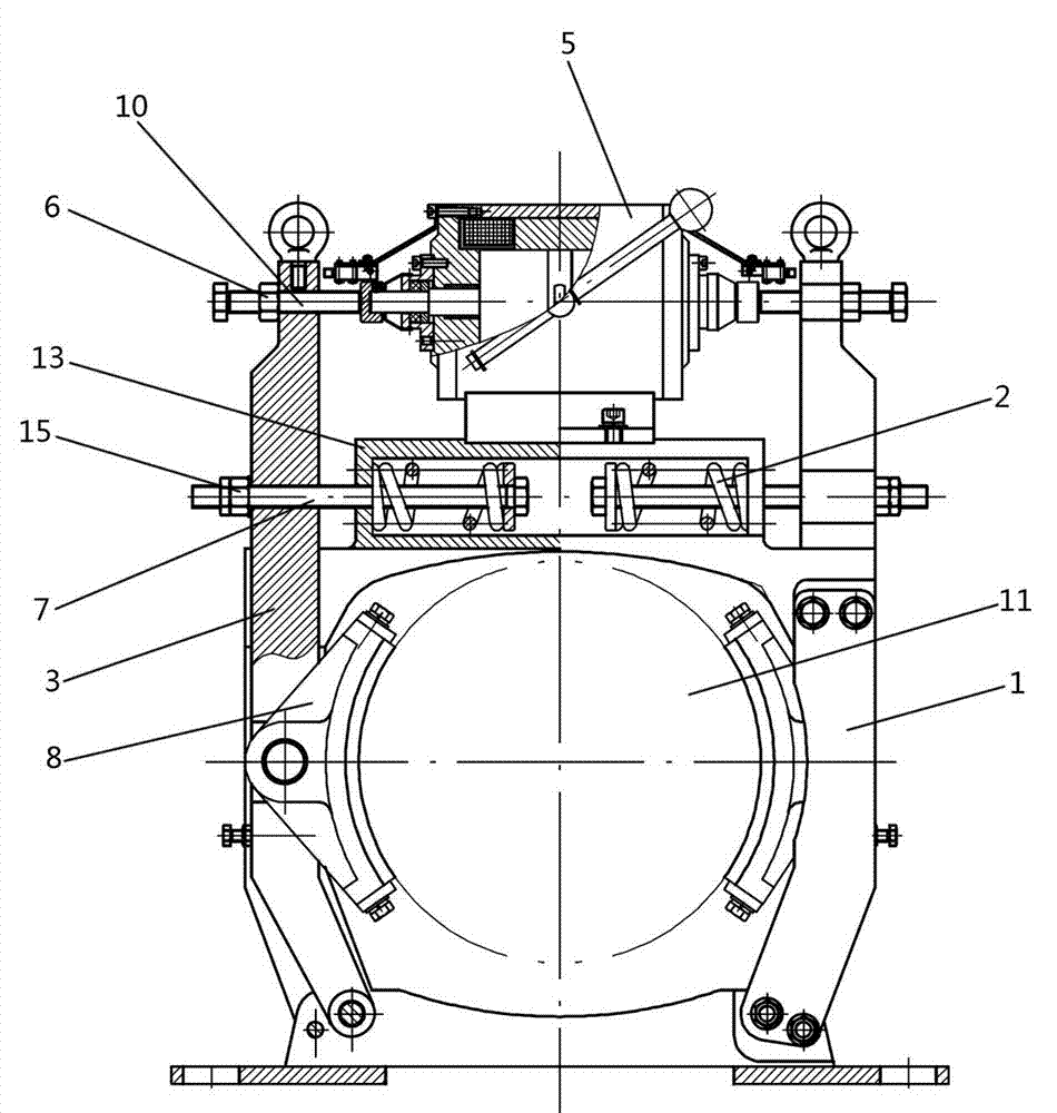
[0041] Such as Figure 4 As shown, the basic structure of the present embodiment is the same as that of Embodiment 1, that is, the gantry support 1 is a rectangular frame that is fixedly connected by the side frame, the top beam and the base, and the double push electromagnet 5 is fixed on the top beam of the gantry support 1, Brake arms 3 are respectively hinged on both sides of the gantry support 1, and brake shoes 8 are connected to the brake arms 3. The concave arc surfaces of the two brake shoes 8 are opposite to the outer circle of the brake wheel 11. The gap adjustment mechanism in this embodiment is an adjusting screw 10 threadedly connected with the transverse screw hole on the brake arm 3, locked on the brake arm 3 by the lock nut 6, and its inner end is against the double-push electromagnet. 5 on the end face (or sheath) of the output shaft.

[0042] The main difference of this embodiment is that the brake spring 2 is changed from an external to a built-in structure,


PUM


Abstract

The invention relates to a binary synchronization electromagnetic block brake of a gantry. The structure of the binary synchronization electromagnetic block brake comprises a gantry bracket, brake arms, brake shoes, a double-push electromagnet, a clearance adjusting mechanism, a draw bar and a brake spring, wherein the gantry bracket is formed by fixedly connected rectangular frames; the brake arms are arranged on two sides of the gantry bracket; the lower end of each brake arm is hinged on the gantry bracket; the brake shoes are connected with the brake arms; the double-push electromagnet is fixed on the gantry bracket; the clearance adjusting mechanism is arranged between the double-push electromagnet and the brake arms for adjusting the clearance between each brake shoe and a brake wheel; the draw bar is connected with the brake arms; the brake spring is sleeved on the draw bar; and the draw bar pulls the brake arms towards the inside by tension force of the brake spring. By virtue of the binary synchronization electromagnetic block brake, the hidden troubles of an elevator traction machine and a crane can be eliminated; the clearance is conveniently adjusted; and the working reliability and universal interchangeability are improved greatly.

Description


Claims


Application Information

Patent Timeline
Owner SHIJIAZHUANG WULON BRAKE
Why Eureka
Try Eureka