Container type data center
A data center, containerized technology, applied in electrical digital data processing, digital data processing components, instruments, etc., can solve the problems of no power generation system, and the air conditioning system is concentrated in the box, so as to achieve reasonable layout and ensure heat dissipation. Effects, full-featured effects
- Summary
- Abstract
- Description
- Claims
- Application Information
AI Technical Summary
Problems solved by technology
Method used
Image

Examples
Embodiment 1
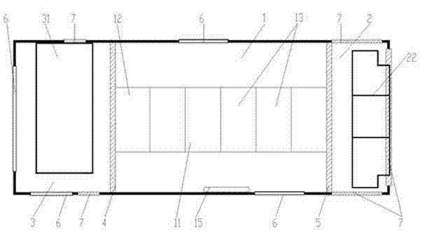
[0038] The present invention provides a container-type data center, the structure of which is as follows: figure 1 As shown, a box body is included, and a door 6 and an air vent 7 are arranged on the side wall of the box body. The box is provided with a main equipment compartment 1, an auxiliary equipment compartment 2 and a power generation compartment 3. The main equipment compartment 1, the auxiliary equipment compartment 2 and the power generation compartment 3 are divided by two partition walls 4,5. The power generation compartment 3 is located on the left side of the partition wall 4, the main equipment compartment 1 is located between the partition wall 4 and the partition wall 5, and the auxiliary equipment compartment 2 is located on the right side of the partition wall 5, that is, the The generator compartment 3 and the auxiliary equipment compartment 2 are located on both sides, and the main equipment compartment 1 is located in the middle.
[0039] A power generatio
Embodiment 2
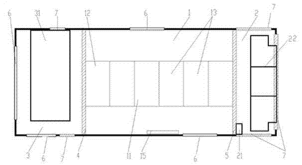
[0043] On the basis of Embodiment 1, this embodiment provides a container-type data center, the structure of which is as follows figure 2 As shown, a monitoring and management system 15 is also installed in the main equipment compartment 1, and a communication access device 21 is installed in the auxiliary equipment compartment 2, and the communication access device 21 is connected to the information technology (IT) equipment cabinet The network communication equipment installed in 11 is connected with the monitoring and management system 15. The network connection between the container data center and the outside is realized, the real-time transmission and exchange of data is realized, and the remote monitoring and management of the container is realized at the same time.
[0044] As a changeable implementation manner, the communication access device 21 may be a wired communication access device or a wireless access device.
Embodiment 3
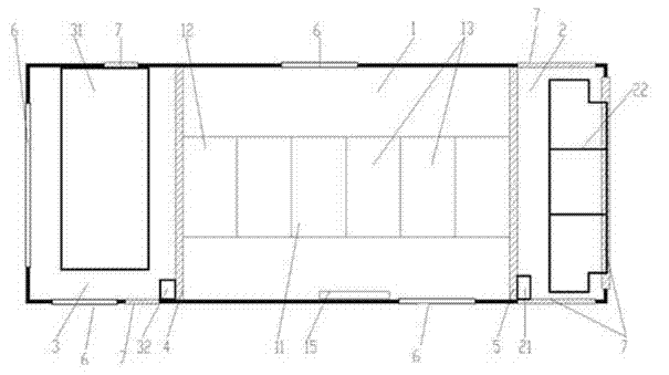
[0046] On the basis of the above-mentioned embodiment 1 and embodiment 2, the container-type data center provided by this embodiment has a structure such as image 3 As shown, in addition to the power generation system 31, the power generation cabin 3 is also provided with a mains power access device 32, and the container data center is connected to the mains power through the mains power connection device 32 to provide power for the data center. The power generation system 31 also includes a generator self-starting control system. When the mains power fails, the generator self-starting control system starts the power generation system 31 to supply power for the data center. Therefore, you can choose to use diesel generators or mains power to power the data center.
[0047] In order to ensure the safety of the equipment inside the main equipment compartment 1, the information technology equipment is arranged in the information technology equipment cabinet 11, and the power distri
PUM
 Abstract
Description
Claims
Application Information
 - R&D Engineer
- R&D Manager
- IP Professional
- Industry Leading Data Capabilities
- Powerful AI technology
- Patent DNA Extraction
Browse by: Latest US Patents, China's latest patents, Technical Efficacy Thesaurus, Application Domain, Technology Topic.
© 2024 PatSnap. All rights reserved.Legal|Privacy policy|Modern Slavery Act Transparency Statement|Sitemap