High-pressure micro-jet carbon supplementing system for microalgae cultivation of raceway pond

A high-pressure micro-spray and runway pool technology, applied in the field of bioengineering, can solve problems such as algae liquid damage and blockage, and achieve the effect of reducing damage, ensuring normal operation, and avoiding blockage.

Active Publication Date: 2013-02-27
GUANGZHOU INST OF ENERGY CONVERSION - CHINESE ACAD OF SCI
View PDF7 Cites 5 Cited by
  • Summary
  • Abstract
  • Description
  • Claims
  • Application Information

AI Technical Summary

Problems solved by technology

These methods do have better results in large-scale cultivation, and can greatly increase CO 2 The utilization efficiency, but this method is to directly pump the algae liquid into the carbon replenishing device through th

Method used


Image

  • High-pressure micro-jet carbon supplementing system for microalgae cultivation of raceway pond
  • High-pressure micro-jet carbon supplementing system for microalgae cultivation of raceway pond

Examples


Embodiment

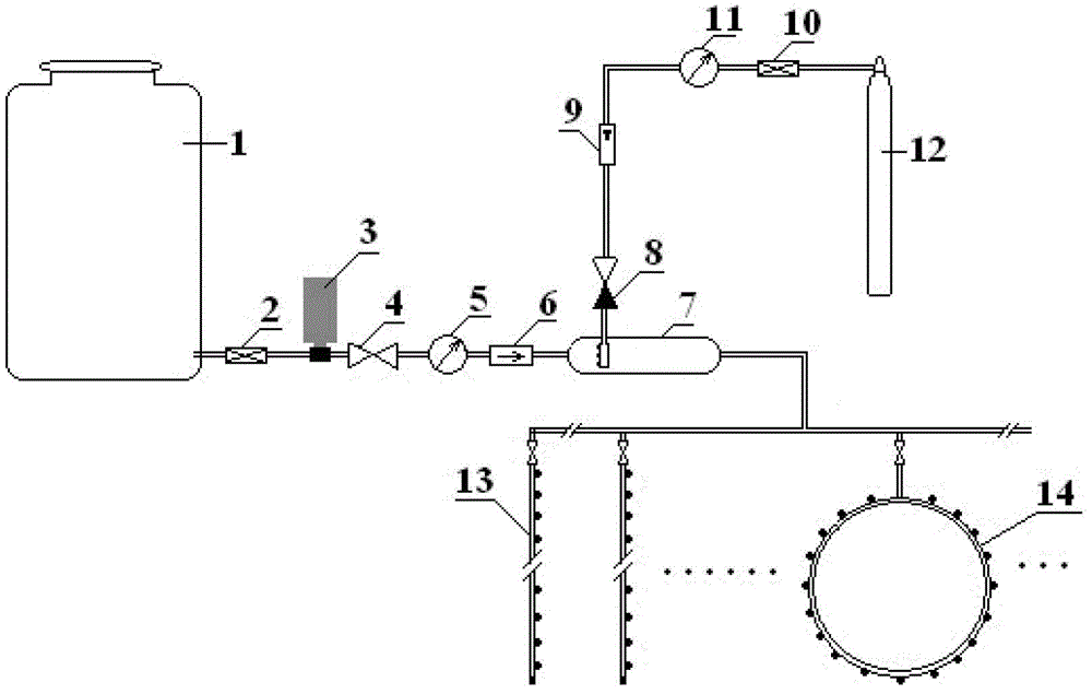
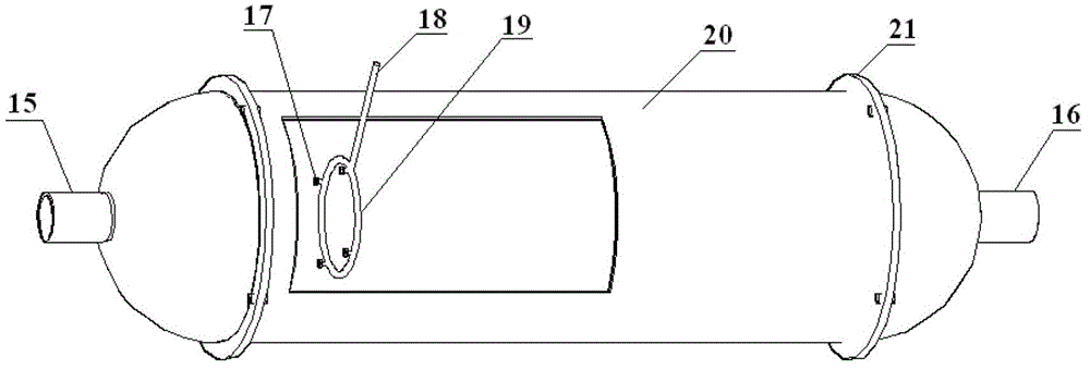
[0028] Such as figure 1 with figure 2 As shown, the high-pressure micro-spraying carbon system for cultivating microalgae in the raceway pond includes a liquid part that provides high-pressure liquid, a high-pressure CO 2 The gas part, the high-pressure micro-spray device 7 and the micro-spray head group. Described high-pressure micro-spray device 7 comprises device housing 20, liquid inlet 15, several micro-spray nozzles 17, gas inlet 18, nozzle disc 19, liquid outlet 16, and housing 20 is metal material or organic material, and its two ends semicircle structure and The intermediate barrel structure is connected by flange 21; the high-pressure liquid enters the high-pressure micro-spray device 7 through the liquid inlet 15 and the CO sprayed by the micro-spray head 17 on the head plate 19. 2 The gas is reversely mixed with the two phases, and the formed fully dissolved CO 2 The liquid enters the micro-spray head group through the liquid outlet 16; the micro-spray head group


PUM


Abstract

The invention provides a high-pressure micro-jet carbon supplementing system for microalgae cultivation of a raceway pond. The high-pressure micro-jet carbon supplementing system a liquid portion, a gas portion, a high-pressure micro-jet device and a micro-sprinkler group, the liquid portion is used for providing high-pressure liquid, the gas portion is used for providing high-pressure CO2, the high-pressure liquid reversely and closely contacts with the high-pressure CO2, solubility of tiny CO2 bubbles formed by micro-jet is increased under the high-pressure condition, the CO2 is sufficiently dissolved in the liquid by adjusting flow of the gas and the liquid, and the liquid with the dissolved CO2 enters the micro-sprinkler group placed in the raceway pond and is eventually released into the raceway pond. The high-pressure micro-jet carbon supplementing system overcomes the shortcoming that a carbon source is directly supplemented in a gaseous CO2 form or by taking microalgae liquid as a CO2 carrier in the cultivation process of an existing raceway pond, and the carbon supplementing system is high in CO2 use ratio, uniform in distribution and simple to mount.

Description


Claims


Application Information

Patent Timeline
Owner GUANGZHOU INST OF ENERGY CONVERSION - CHINESE ACAD OF SCI
Why Eureka
Try Eureka