Electric drive lifting unmanned flying platform

A flying platform and electric drive technology, applied to aircraft, lighter-than-air aircraft, motor vehicles, etc., can solve problems such as inability to carry out lifting operations, inability to use hoisting, battery capacity and output power limitations, etc.

Inactive Publication Date: 2013-03-20
上海交通大学无锡研究院
View PDF6 Cites 5 Cited by
  • Summary
  • Abstract
  • Description
  • Claims
  • Application Information

AI Technical Summary

Problems solved by technology

[0002] Existing lifting equipment is usually vehicle-mounted lifting machinery, but this type of lifting machinery is limited by the length of the boom, needs to be close to heavy objects, and requires solid ground conditions
When these conditions are

Method used


Image

  • Electric drive lifting unmanned flying platform

Examples


Embodiment Construction

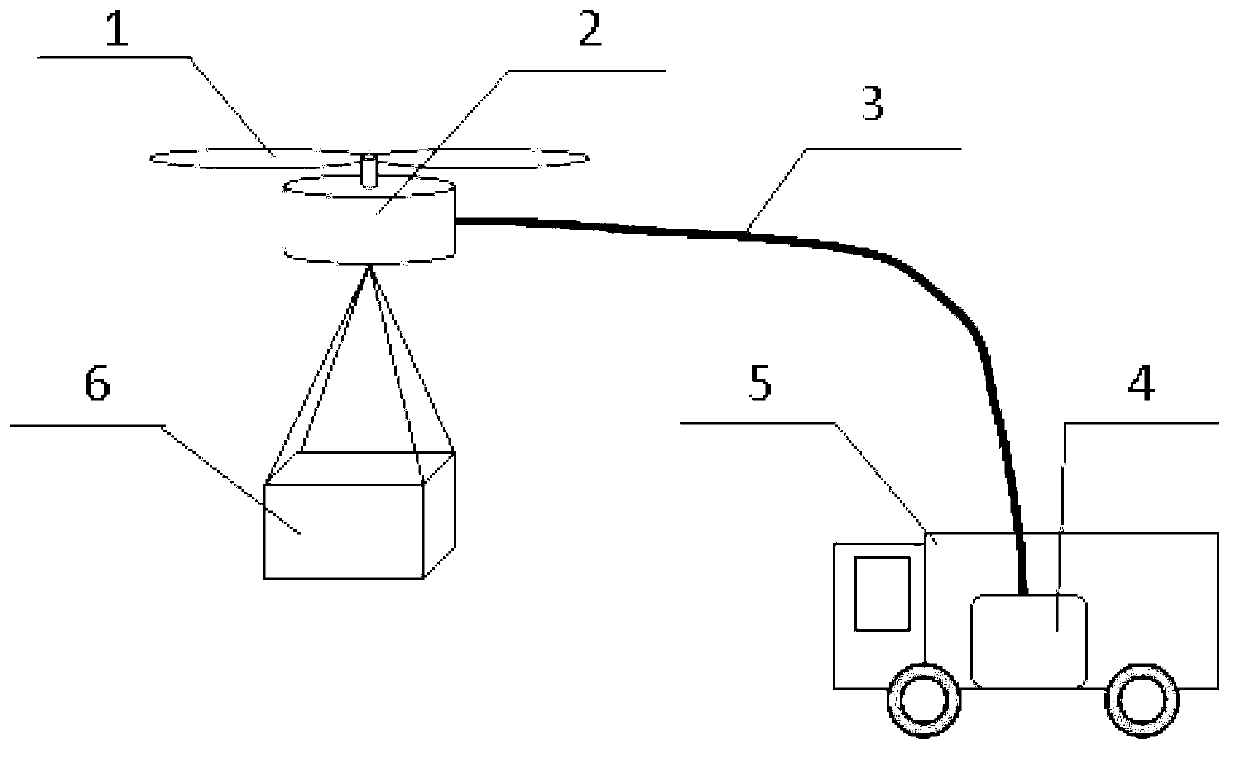
[0010] Such as figure 1 An electric-driven lifting unmanned flying platform is shown, including an electric-driven lifting unmanned aerial vehicle. The electrically driven lifting drone includes a motor 2 and a propeller 1 . The unmanned aerial vehicle is connected with the on-board power supply 4 that the ground power supply vehicle 5 has through the power transmission cable 3, and is driven by the power supply of the ground power supply vehicle 5, and lifts the heavy object 6.

[0011] Since the UAV is powered by the ground, it solves the problem of the power and duration of the onboard battery power supply. The ground power supply vehicle can provide enough power and duration for the UAV to lift heavy objects, and the UAV can be used for power transmission. Lifting operations within the scope of the cable length. The vehicle-mounted power supply is also easy to move, and the flying platform can be widely used in places that cannot be reached by conventional vehicle-mounted l


PUM


Abstract

The invention discloses an electric drive lifting unmanned flying platform. The electric drive lifting unmanned flying platform is characterized by comprising an electric drive lifting unmanned machine, wherein the electric drive lifting unmanned machine is connected with a ground power supply device through a transmission cable and is driven by the ground power supply device in a power-supply mode. Preferably, the ground power supply device is a power supply vehicle with a vehicle power supply. Continuous power supplying is conducted to the electric drive lifting unmanned machine through a ground power supply, and thus the power and the duration time of power supplying are guaranteed, and heavy articles can be lifted by relying on the lift force of a propeller. Moreover, the unmanned machine can conduct lifting operation within the length scope of the transmission cable, and can be flexibly applied to various occasions.

Description


Claims


Application Information

Patent Timeline
Owner 上海交通大学无锡研究院
Why Eureka
Try Eureka