Vehicular grab hook

An arc arch and chute technology, applied in the field of vehicle grab hooks, can solve problems such as low safety, single function, time-consuming and labor-intensive, and achieve the effect of saving time and labor

Inactive Publication Date: 2013-04-03
QINGDAO RUIFENG GAS
View PDF4 Cites 0 Cited by
  • Summary
  • Abstract
  • Description
  • Claims
  • Application Information

AI Technical Summary

Benefits of technology

This technology helps save money while making it easier for people who want their own carbons up quickly or at home. It also makes things smarter with less effort compared to traditional methods like buying new cars that have been designed specifically for each model being used instead of purchasing one from scratch. Additionally, this system can be easily adapted based on how big they're carrying them around inside vehicles without causing any damage during use.

Problems solved by technology

The technical problem addressed by this patented technology relates to improving upon existing vehicles' mountable bottleneck grip systems with limited functionality or high risk due to their fixed design.

Method used


Image

  • Vehicular grab hook

Examples


Embodiment Construction

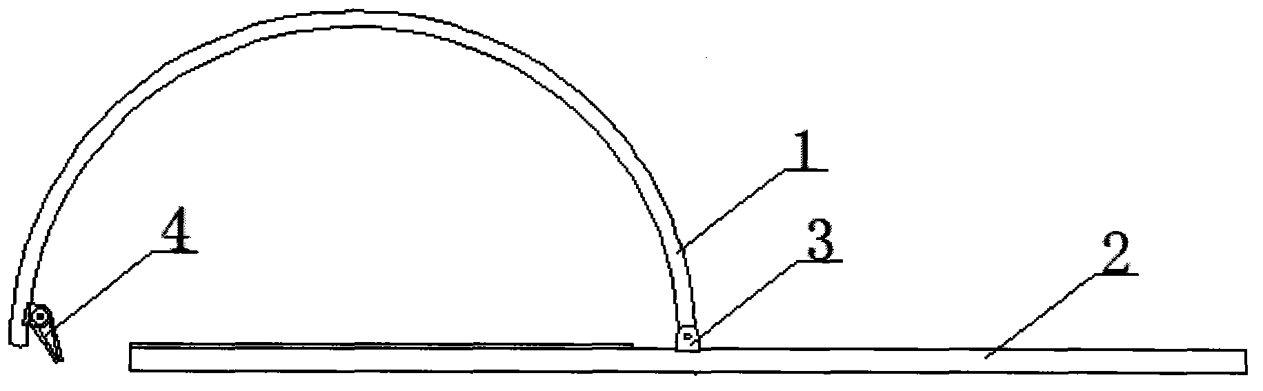
[0013] Below in conjunction with accompanying drawing and example the present invention will be further described:

[0014] like figure 1 As shown, a vehicle-mounted grapple includes: an arc arch, a handle, a chute device and an end plate device, the arc arch is connected with the chute device through a sliding connection, the chute device is mobile connected to the handle body, and the chute The device is connected to the inner side of the arc arch through a mobile connection, the end plate device is slidably connected to the chute device, the end plate device is connected to one end of the arc arch through bolts, and the position of the arc arch is adjusted through the chute device.

[0015] Preferably, the fixed position of the arc arch on the handle can be adjusted through the sliding groove device.

[0016] Preferably, the end plate device can be disassembled to replace the rubber skin.

[0017] Preferably, the handle fixes the arch and the vehicle bottle.

[0018] The in


PUM


Abstract

The invention relates to a vehicular grab hook, which comprises an arch, a handle, a slide groove device and an end plate device, wherein the arch is slidingly connected with the slide groove device, the slide groove device is movably connected with a surface body of the handle, the slide groove device is movably connected with the inner side of the arch, the end plate device is slidingly connected with the slide groove device, the end plate device is connected with one end of the arch by a bolt, and the position of the arch is adjusted by the slide groove device. The vehicular grab hook has the advantages that the time and the labor are saved, more safety and convenience are realized, the adjusting is more reasonable according to the size of a vehicular cylinder, and more environment-friendly and energy-saving effects are realized by recycling.

Description


Claims


Application Information

Patent Timeline
Owner QINGDAO RUIFENG GAS
Why Eureka
Try Eureka