Power transmission device of rootstock excavator

A transmission device and mechanical power technology, applied in transmission devices, excavator harvesters, harvesters and other directions, can solve the problems of high maintenance cost, large energy consumption, large volume, etc., and achieve stable and reliable work, simple structure and high efficiency. Effect

Inactive Publication Date: 2013-06-12
宋四泉
View PDF6 Cites 2 Cited by
  • Summary
  • Abstract
  • Description
  • Claims
  • Application Information

AI Technical Summary

Problems solved by technology

Such a structure has the following disadvantages due to its unreasonable structure: 1. The gearbox is heavy and bulky; 2. The energy consumption is large and the stability is poor; 3. The long shaft of the crank at both end

Method used


Image

  • Power transmission device of rootstock excavator

Examples


Embodiment Construction

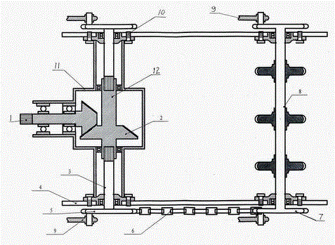
[0008] The embodiment is described in detail in conjunction with the above accompanying drawings. It includes two side beams 4 fixed to the body, a reduction box 11 is fixedly connected with a bolt 10 between the front ends of the two side beams, and a reduction box 11 is fixed between the two side beam rear ends. The bolt and the bearing seat are installed with an endless chain box transmission shaft 8, a pair of bridge sector gears 2 are installed in the reduction box, and a power input shaft 1 protruding forward is installed on the bridge sector gears at the front of the reduction box , a semi-floating half-shaft 3 is respectively connected to the output shafts 12 at both ends of the bridge-type sector gear at the back, and the outer ends of the two semi-floating half-shafts protrude from the reduction box through the bearing seat to the outside of the side beam respectively. A sprocket 5 is respectively installed on the outer end of each semi-floating half shaft, a rear sprock


PUM


Abstract

The invention discloses a power transmission of a rootstock excavator, which is characterized in that a reduction box is connected between the front ends of two boundary beams; a circular chain box transmission shaft is mounted between the rear ends of the two boundary beams by bolts and bearing supports; a pair of bridge sector gears is mounted in the reduction box; a power input shaft extending from the front of the reduction box is mounted on the bridge sector gear in the front of the reduction box; output shafts at the two ends of the bridge sector gear at the back are connected with semi-floating half shafts respectively; the outer ends of the two semi-floating half shafts extend out of the boundary beams from the interior of the reduction box through bearing supports; a chain wheel is mounted at the outer end of each semi-floating half shaft; a rear chain wheel is mounted at each of the two ends of the circular chain box transmission shaft; power output crankshaft connecting rods are respectively mounted on the chain wheels; and a chain is connected between the front chain wheel and the rear chain wheel on one side. The power transmission has the advantages of simple structure, light weight, small size, low energy consumption, high efficiency, low noise and stable and reliable operation.

Description


Claims


Application Information

Patent Timeline
Owner 宋四泉
Why Eureka
Try Eureka