Aerial optical cable

An overhead optical cable and optical fiber technology, which is used in optical fiber/cable installation, stamps, instruments, etc., can solve the problems of inconvenient maintenance, maintenance, and difficult maintenance of optical fibers and cables, and achieves low maintenance cost, high finished product qualification rate, and convenient maintenance. Effect

Active Publication Date: 2013-12-25
STATE GRID CORP OF CHINA +3
View PDF2 Cites 23 Cited by
  • Summary
  • Abstract
  • Description
  • Claims
  • Application Information

AI Technical Summary

Benefits of technology

The technical effect of this patented technology lies at creating an identifying device that can be easily attached or worn by any type of object such as poles without being difficult for them to see due to its unique design fused onto one part of the suspended wires' surface. This makes it easier to find objects like lights when they shouldn’t go out because there will always have some kind of colored markings visible from outside. Additionally, these devices won't get damaged overtime while still providing their benefits.

Problems solved by technology

This patented technical problem addressed by this patents relates to how easily users may want different types of opaque wires (optics) from one another without having them mixed up together when they use an Optrolled Cable System Interface Express® protocol).

Method used


Image

  • Aerial optical cable
  • Aerial optical cable
  • Aerial optical cable

Examples


Embodiment 1

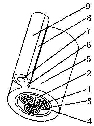
[0026] please see figure 1 and figure 2 , an overhead optical cable, which includes a central strength member 4, three loose tubes 2 distributed around the outer edge of the central strength member, a moisture barrier layer 3 coated outside the loose tube, and an extrusion coating outside the moisture barrier layer The outer sheath 5 has six optical fibers 1 in the loose tube, which is characterized in that: outside the outer sheath, there is also a suspender layer 9, inside the suspender layer there is a suspension reinforcement 7, and the suspender layer and the outer sheath pass through the connecting rib 6 connected, the suspender layer on both sides of the suspension reinforcement has identification strips 8 embedded in the suspender layer and having different colors from the suspender layer, the suspender layer and the outer sheath are distributed in parallel in space, and the suspender layer, the outer sheath, The materials of the connecting ribs are the same, and the su

Embodiment 2

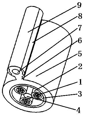
[0028] please see image 3 and Figure 4 , and refer to figure 1 and figure 2 , an aerial optical cable, which is basically the same as the implementation example 1, the difference is that there are 4 optical fibers in the loose tube, and the adjacent loose tubes are not tangent. In this case, a larger center can be used The strength member is used to overcome the problems that the central strength member of too small size is easy to break during the production of the optical cable and the yield of the finished product is low; at the same time, the tensile resistance of the optical cable is enhanced.

Embodiment 3

[0030] please see Figure 5 , and refer to Figure 1 to Figure 4 , an overhead optical cable, which is basically the same as that in Example 2, the difference lies in: the shape of the identification strip, which is easier to produce.

[0031] Of course, for the aerial optical cable described in the above-mentioned implementation examples 1-3, the loose tube can also be other multiples greater than 3; the optical fiber in each loose tube can be at least one; each loose tube is Tangent to the central reinforcement, each loose tube is tangent to the moisture barrier.

[0032] Of course, further, in the aerial optical cable mentioned above, the adjacent loose tubes are preferably tangent; they can also be non-tangent. In this case, only the size of the central strengthening member needs to be increased.


PUM


Abstract

The invention relates to the technical field of cables, in particular to an aerial optical cable. The aerial optical cable comprises a central reinforcing part, at least three loose sleeves, damp-proof layers and outer protective layers, wherein the loose sleeves are distributed around the peripheryof the central reinforcing part, the damp-proof layers wrap the loose sleeves, the outer protective layers wrap the damp-proof layers in an extrusion molding mode, and at least one optical fiber is arranged in each loose sleeve. The aerial optical cable is characterized in that a hanging wire layer is arranged outside each outer protective layer, a hanging reinforcing part is arranged in each hanging wire layer, each hanging wire layer is connected with each outer protective layer through a connection rib, the hanging wire layers on two sides of each hanging wire reinforcing part are provided with identification strips, the identification strips are embedded into the hanging wire layers and have different colors with the hanging wire layers, the hanging wire layers and the outer protective layers are distributed in parallel in space, the hanging wire layers, the outer protective layers and the connection ribs are made of the same material, and the hanging wire layers, the outer protective layers, the connection ribs and the identification strips are formed in an integrated mode. The aerial optical cable has the advantages of being easy to identify, maintain and repair, low in maintaining cost, easy to manufacture, and high in percent of pass of finished products.

Description


Claims


Application Information

Patent Timeline
Owner STATE GRID CORP OF CHINA
Why Eureka
Try Eureka