Connecting ring of filter support

A filter and lens technology, applied in the direction of filter, installation, optics, etc. for photographic purposes, can solve the problems of reducing the number, scratching other lenses, and hindering the matching of filters, to increase the number, improve functionality, reduce Effects of light leaks

Inactive Publication Date: 2014-01-15
DONGGUAN BORUI FILTER EQUIP
View PDF5 Cites 5 Cited by
  • Summary
  • Abstract
  • Description
  • Claims
  • Application Information

AI Technical Summary

Benefits of technology

This patented technology allows an optical device called LCPE (Liquid Crystal Display Panel) camera that uses different types of filters attached by means like cables. It includes a special feature where there are two parts - a fixed part made up of a mounting plate and a plug-in component used together to secure these components during assembly. A stop member helps prevent accidentally shifting them back into place while still allowing it easy access. By combining this design with direct installation onto the filter regulation loop, the cameras have improved performance without sacrificing their ability to receive high definition images due to reduced glare caused from reflected sunlight. Additionally, because they don't require any extra equipment such as mirrors or prismatic films, they may now work better if equipped with various advanced technologies like liquid crystals or LED lights.

Problems solved by technology

This patented technical problem addressed in this patents relates to improving the functionality and flexibility of existing filtration devices due to their use as auxiliaries during specialized photographings like videos. However, current methods require frequent changes over multiple filters, making them difficult to meet new demanders who want more versatility than just plain filtering out unwanted colors.

Method used


Image

  • Connecting ring of filter support
  • Connecting ring of filter support
  • Connecting ring of filter support

Examples


Embodiment Construction

[0022] The present invention will be described in further detail below in conjunction with the accompanying drawings.

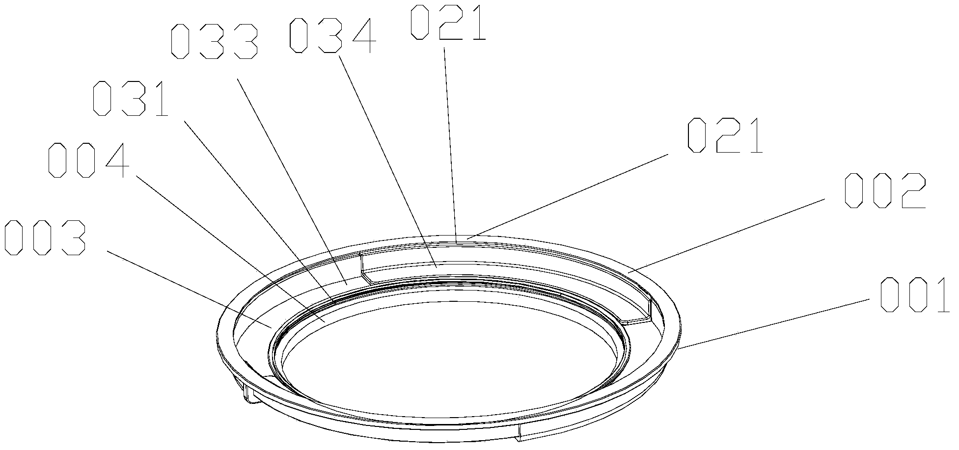
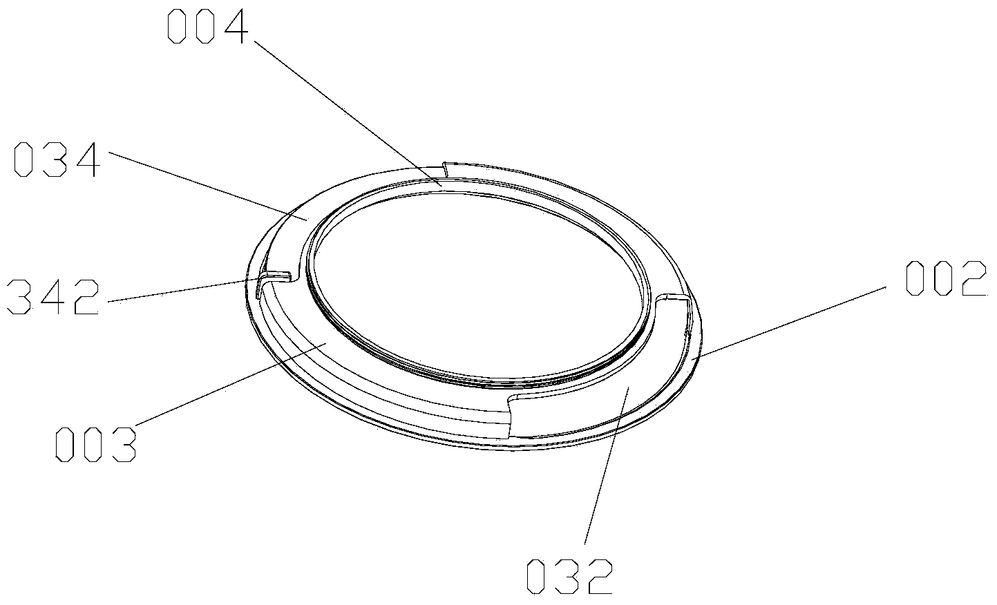
[0023] figure 1 A filter holder adapter according to the present invention is schematically shown.

[0024] According to one aspect of the present invention, a filter holder adapter is provided, including an adapter body 001, wherein in this embodiment, the adapter body 001 is integrally formed by 6061T aluminum alloy through precision machining, and the above-mentioned adapter body 001 includes The fixed ring 002, the filter adjustment ring 003 and the lens adapter ring 004 are arranged in order from top to bottom. The surface of the adapter body 001 is hard anodized to form a hard oxide film layer, and the 6061T aluminum alloy is used to ensure that the adapter body 001 At the same time, it ensures the pressure resistance, wear resistance and low temperature resistance of the ring body 001, and it will not be deformed after long-term use. A hard oxide film la


PUM


Abstract

The invention discloses a connecting ring of a filter support. The connecting ring comprises a connecting ring body, the connecting ring body comprises a fixing ring, a filter adjustment ring and a lens connecting ring, the fixing ring, the filter adjustment ring and the lens connecting ring are sequentially connected from top to bottom, an inner ring body of the fixing ring is connected with the filter adjustment ring, the fixing ring is used for being connected with the filter support, the filter adjustment ring is a ring body with the L-type cross section, a filter connecting end is arranged on an inner ring body at the lower end of the filter adjustment ring, an adjustment window is arranged in the end face of the periphery of the filter connecting end, one end of the lens connecting ring is a lens connecting end, and the other end of the lens connecting ring is connected with the filter adjustment ring. According to the connecting ring of the filter support, the fixing ring, the filter adjustment ring and the lens connecting ring are combined, installation is easily and rapidly achieved, a CPL or other filters can be directly installed on the filter adjustment ring, the angles of the CPL can be flexibly adjusted through the adjustment window, and the connecting ring is rapid and convenient to use.

Description


Claims


Application Information

Patent Timeline
Owner DONGGUAN BORUI FILTER EQUIP
Why Eureka
Try Eureka