Pretreatment device and pretreatment method for transformer oil

A pretreatment device and transformer oil technology, applied in the preparation of test samples, etc., can solve problems such as low efficiency, large nitrogen consumption, waste, etc., and achieve the effects of saving usage, reducing test costs, and quick preparation

Active Publication Date: 2014-03-05
STATE GRID CORP OF CHINA +1
View PDF9 Cites 10 Cited by
  • Summary
  • Abstract
  • Description
  • Claims
  • Application Information

AI Technical Summary

Problems solved by technology

The current pretreatment process mainly uses nitrogen to stir and bubble the original oil sample, which

Method used


Image

  • Pretreatment device and pretreatment method for transformer oil

Examples


Embodiment Construction

[0035] The present invention will be described in further detail below in conjunction with the accompanying drawings.

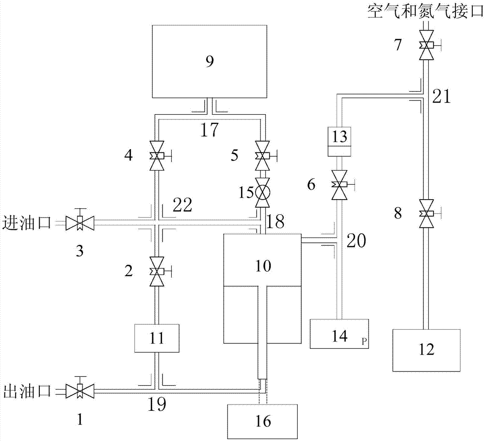
[0036] Such as figure 1 , the present invention provides a pretreatment device for transformer oil, said device includes a solenoid valve, a ball valve 15, an oil tank 9, an oil cylinder 10, a circulating pump 11, a vacuum pump 12, an oil-gas separation chamber 13, a pressure sensor 14, a stepping motor 16, Air and nitrogen interface, oil inlet and oil outlet; The oil inlet is connected with the oil tank 9, the oil cylinder 10 and the circulating pump 11 through a cross 22; the oil cylinder 10 is separated from the oil tank 9 and the oil and gas The chamber 13 is connected with the pressure sensor 14 respectively, and the ball valve 15 is arranged between the oil tank 9 and the oil cylinder 10; the piston of the oil cylinder 10 is fixedly connected with the stepping motor 16 through a mechanical device, and the bottom of the piston connected to the oil outlet;


PUM

PropertyMeasurementUnit
Diameteraaaaaaaaaa
Diameteraaaaaaaaaa

Abstract

The invention provides a pretreatment device and a pretreatment method for transformer oil. The pretreatment device comprises an electromagnetic valve, a ball valve, an oil tank, an oil cylinder, a circulating pump, a vacuum pump, an oil-gas separation chamber, a pressure sensor, a stepping motor, an air and nitrogen interface, an oil inlet and an oil outlet, wherein the oil inlet is connected with the oil tank, the oil cylinder and the circulating pump through four-way pieces, the oil cylinder is respectively connected with the oil tank, the oil-gas separation chamber and the pressure sensor, the ball valve is arranged between the oil tank and the oil cylinder, a piston of the oil cylinder is fixedly connected with the stepping motor through a mechanical device, the bottom of the piston is connected with the oil outlet, and the oil-gas separation chamber is connected with the air and nitrogen interface, and connected with the vacuum pump through the electromagnetic valve. According to the pretreatment device and the pretreatment method, the transformer oil is pretreated by introducing three degassing methods such as vacuum atomization degassing, air cleaning and nitrogen cleaning, so that the deficiency of cleaning and degassing effects of various methods can be made up, and residual gases dissolved in original transformer oil can be eluted efficiently.

Description


Claims


Application Information

Patent Timeline
Owner STATE GRID CORP OF CHINA
Why Eureka
Try Eureka