Telemetric sample data definition monitoring method for scheduling energy management system (EMS)

A technology of telemetry sampling and data definition, applied in database indexing, data processing applications, structured data retrieval, etc., can solve problems such as heavy work tasks, heavy work, and complicated work for automated personnel, achieving high accuracy and increasing practicability Effect

Inactive Publication Date: 2014-03-12
SHANGHAI MUNICIPAL ELECTRIC POWER CO
View PDF3 Cites 0 Cited by
  • Summary
  • Abstract
  • Description
  • Claims
  • Application Information

AI Technical Summary

Benefits of technology

The technical effect that this technology helps save on manual searches by providing accurate data with increased efficiency compared to existing systems.

Problems solved by technology

This patented describes an issue where there may exist difficulties when performing certain types of maintenance on electric systems due to large amounts of time required by manual workers or lack of knowledge about their technical problem addressed during these works.

Method used


Image

  • Telemetric sample data definition monitoring method for scheduling energy management system (EMS)

Examples


Embodiment Construction

[0016] The present invention will be further elaborated below by describing a preferred specific embodiment in detail in conjunction with the accompanying drawings.

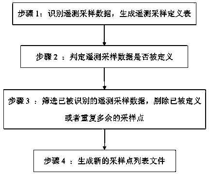
[0017] Such as figure 1 As shown, a dispatching EMS system telemetry sampling data definition monitoring method includes:

[0018] Step 1: The telemetry sampling devices installed at all sampling points in the power grid system send telemetry data to the dispatching EMS system, identify the telemetry sampling data, and generate a telemetry sampling definition table.

[0019] Step 2: Scheduling the EMS system to determine whether the telemetry sampling data described in step 1 is defined, the determination method is: compare the telemetry sampling definition table generated in step 1 with the original sampling point list file in the system to determine Whether the sampling point corresponding to the telemetry sampling data is defined.

[0020] Step 3: Screen the telemetry sampling data determined to have been ident


PUM


Abstract

The invention discloses a telemetric sample data definition monitoring method for a scheduling energy management system (EMS). The method comprises the following steps that 1, telemetric sampling devices arranged on all sampling sites in a grid system send telemetric data to the scheduling EMS, telemetric sample data are identified and a telemetric sample definition list is generated; 2, the scheduling EMS judges whether the telemetric sample data in the step 1 are defined; 3, the telemetric sample data which are judged to be identified in the step 2 are screened, and the defined or redundant sampling sites are removed; 4, the scheduling EMS system generates a new sampling site list file according to sampling sites corresponding to the removed undefined telemetric sample data in the step 3. By the method, a great amount of time required by manually searching the undefined sampling sites is saved, the method has high accuracy, and the practicability of filling leak of scheduling automation work is improved.

Description


Claims


Application Information

Patent Timeline
Owner SHANGHAI MUNICIPAL ELECTRIC POWER CO
Why Eureka
Try Eureka