Clamping device of PIN diode reverse bias current detection tool

A technology for detecting tooling and reverse bias current, applied in sorting and other directions, can solve problems such as poor practicability and low detection efficiency, and achieve the effect of improving practicability and improving detection efficiency

Active Publication Date: 2021-05-28
江苏长弘半导体有限公司
View PDF7 Cites 0 Cited by
  • Summary
  • Abstract
  • Description
  • Claims
  • Application Information

AI Technical Summary

Problems solved by technology

[0002] Before using the PIN diode, it needs to be tested to screen out unqualified components. Among them, the detection of the leakage current index of the PIN t

Method used


Image

  • Clamping device of PIN diode reverse bias current detection tool
  • Clamping device of PIN diode reverse bias current detection tool
  • Clamping device of PIN diode reverse bias current detection tool

Examples


Example Embodiment

[0019]DETAILED DESCRIPTION OF THE PREFERRED EMBODIMENTS The following examples are intended to illustrate the invention, but are not intended to limit the scope of the invention.

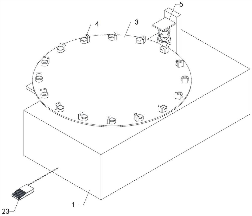
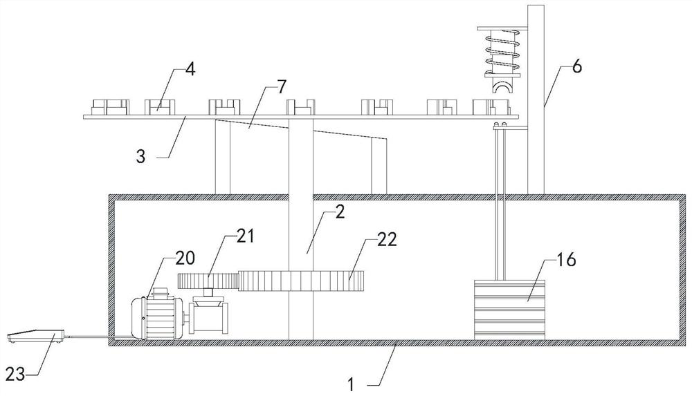
[0020]Such asFigure 1 to 5As shown, the clamping device of the PIN 2-stage tube reverse bias current detecting the tool, including the apparatus box 1, the rotating shaft 2, the turntable 3, several group detecting seats 4, detecting device 6, retracting device 7, and driving device The rotating shaft 2 is rotated to be mounted on the apparatus box 1, and the turntable 3 is fixedly mounted on the top end of the apparatus box 1, the axis of the turntable 3 and the axis of the equipment box 1, the drive device is mounted in the apparatus box 1 for driving the shaft 2 The axis rotates, and several group detecting seats 4 are uniformly attached to the top edge of the turntable 3, and the detecting seat 4 is provided with a jack 5 through the turntable 3 for detecting the PIN Level Tube. The detecting device 6 is mo


PUM


Abstract

The invention relates to the technical field of diode production, in particular to a clamping device of a PIN diode reverse bias current detection tool, which improves the detection efficiency of a PIN diode and improves the practicability. The clamping device comprises an equipment box, a rotating shaft, a rotating disc, a plurality of groups of detection bases, a detection device, a material returning device and a driving device, wherein the rotating shaft is rotatably installed on the equipment box, the rotating disc is fixedly installed at the top end of the equipment box, the axis of the rotating disc and the axis of the equipment box are collinear, the driving device is disposed in the equipment box and configured to drive the rotating shaft to rotate around the axis, the detection bases are evenly and fixedly installed on the edge of the top end of the rotating disc, insertion holes penetrating through the rotating disc are formed in the detection bases so that pins of the PIN diode can penetrate through the insertion holes, the detection device used for detecting the PIN diode is installed on the equipment box, and the material returning device used for returning the detected PIN diode from the detection bases is installed on the equipment box.

Description


Claims


Application Information

Patent Timeline
Owner 江苏长弘半导体有限公司
Why Eureka
Try Eureka