Pressure switch state detection circuit, circuit board, and electric heating product with circuit board

A pressure switch and state detection technology, applied in circuit breaker testing, circuits, pressure cookers, etc., can solve the problems of difficult circuit implementation, many devices, and increased difficulty of circuit boards, and achieve the effect of simple state detection circuits

Active Publication Date: 2014-03-26
MIDEA GRP CO LTD +1
View PDF5 Cites 6 Cited by
  • Summary
  • Abstract
  • Description
  • Claims
  • Application Information

AI Technical Summary

Problems solved by technology

[0002] Household electric heating products usually use heating wire to heat objects, but at present, due to the influence of voltage changes, for example, the change of voltage comes from power interference during power transmission, these household electric heating products that use heating wire to heat cannot do Precise power control. At present, in order to solve the problem of voltage change, researchers in the industry have proposed to step down the input voltage first, and then divide part of the voltage signal by the voltage divider circuit, and then perform voltage detection after passing through the filter c

Method used


Image

  • Pressure switch state detection circuit, circuit board, and electric heating product with circuit board
  • Pressure switch state detection circuit, circuit board, and electric heating product with circuit board
  • Pressure switch state detection circuit, circuit board, and electric heating product with circuit board

Examples


Embodiment Construction

[0044] The technical scheme of the present invention will be described in further detail below in conjunction with the accompanying drawings and specific examples, so that those skilled in the art can better understand the present invention and implement it, but the examples given are not intended to limit the present invention .

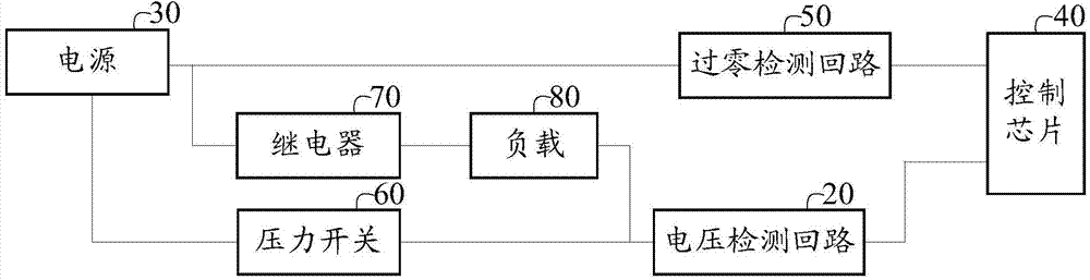
[0045] Such as figure 1 As shown, a pressure switch state detection circuit provided by an embodiment of the present invention includes:

[0046] power supply 30;

[0047] The zero-crossing detection circuit 50, its input end is connected to the power supply, and its output end is connected to the zero-crossing signal detection terminal ZERO of the control chip 40;

[0048] A relay 70, one end of which is connected to the power supply 30, and the other end is connected to one end of the load 80;

[0049] A load 80, the other end of which is connected to the input end of the voltage detection circuit 20;

[0050] The voltage detection circuit 20, it


PUM


Abstract

The invention discloses a pressure switch state detection circuit, a circuit board and an electric heating product with the circuit board. The pressure switch state detection circuit comprises a power source, a zero-cross detection circuit, a relay, a load, a voltage detection circuit and a pressure switch; the input end of the zero-cross detection circuit is connected to the power source, and the output end of the zero-cross detection circuit is connected with a zero-cross signal detection terminal ZERO of a control chip; one end of the relay is connected to the power source, and the other end of the relay is connected with one end of the load; the other end of the load is connected to the input end of the voltage detection circuit; the input end of the voltage detection circuit is further connected to the pressure switch, and the output end of the voltage detection circuit is connected with a voltage detection signal input terminal AD-V of the control chip; one end of the pressure switch is connected to the power source, and the other end of the pressure switch is connected to the input end of the voltage detection circuit. According to the pressure switch state detection circuit, the zero-cross detection circuit (Zero-Cross) is connected to the upper end of the relay, the pressure switch K1 is connected to the other end of a heater, and the voltage detection circuit is connected between the heater and the pressure switch K1. Detection of various signals is achieved through time-sharing detection and combined judgment, and therefore the pressure switch state detection circuit is simple.

Description


Claims


Application Information

Patent Timeline
Owner MIDEA GRP CO LTD
Why Eureka
Try Eureka