Sewage sludge separation treatment equipment

A technology for separation and treatment of sewage sludge, which is applied in the fields of sludge treatment, water/sewage treatment, dehydration/drying/concentrated sludge treatment, etc. Need to wait for the problem to achieve the effect of significant crushing effect and good mixing effect

Inactive Publication Date: 2021-05-07
吴江市绿源环保科技有限公司
View PDF0 Cites 5 Cited by
  • Summary
  • Abstract
  • Description
  • Claims
  • Application Information

AI Technical Summary

Benefits of technology

This patented device helps separate waste materials such as paper scraps (pulp) through various techniques including mechanical processing methods for recycling purposes. It uses two motors - one acts upon an upper part called the grinding mechanism, allowing it to break up larger pieces of material before being sent downstream. Another motor operates another machine called the paddle drive system, causing movement within the apparatus itself. A special type of fluid tank supplies clean hydraulic oil during this process. By controlling these movements, the apparator can efficiently mix different types of liquids together without getting stuck due to solid particles. Additionally, there are also mechanisms inside the appararus design to improve its performance over time. Overall, this technology allows efficient use of resource sources and saves power consumption compared to traditional disposal processes.

Problems solved by technology

This patented technical problem addressed in this patents relates to improving the efficiency and effective removal of municipal wastewater-treatment plant (WTS) effluent with high levels of solids content such as bacteria, yeast cells, silt particles, clay residue, oil fractions, fats, grease, oily substances, organic acids, ammonium salts, calcium carbonate, magnesite, iron oxide, silica gel, rust powder, metal chelating agents, pesticides, dyes, volatile compounds like alcohols, aldehydes, ketones, esters, carboxylic acid derivatives, hydrocarbons, sulfur dioxins, nitrification products, polynuclear biomolecules, tannin polymer molecule fragments, polycycloalkanes, cyclooxane rings, aliphatic chemical structures containing these groups, and other harmful materials found within them. These pollutants have negative impact upon human health due to their potential hazards when released during landfill disposal processes. Existing methods involve physical separators but they often result in incomplete cleanings leading to secondary contamination issues. There is an urgent need for better ways to remove unwanted material without causing damage to downstream components.

Method used


Image

  • Sewage sludge separation treatment equipment
  • Sewage sludge separation treatment equipment
  • Sewage sludge separation treatment equipment

Examples


Embodiment 1

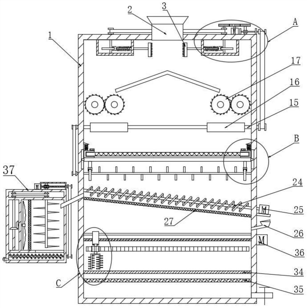
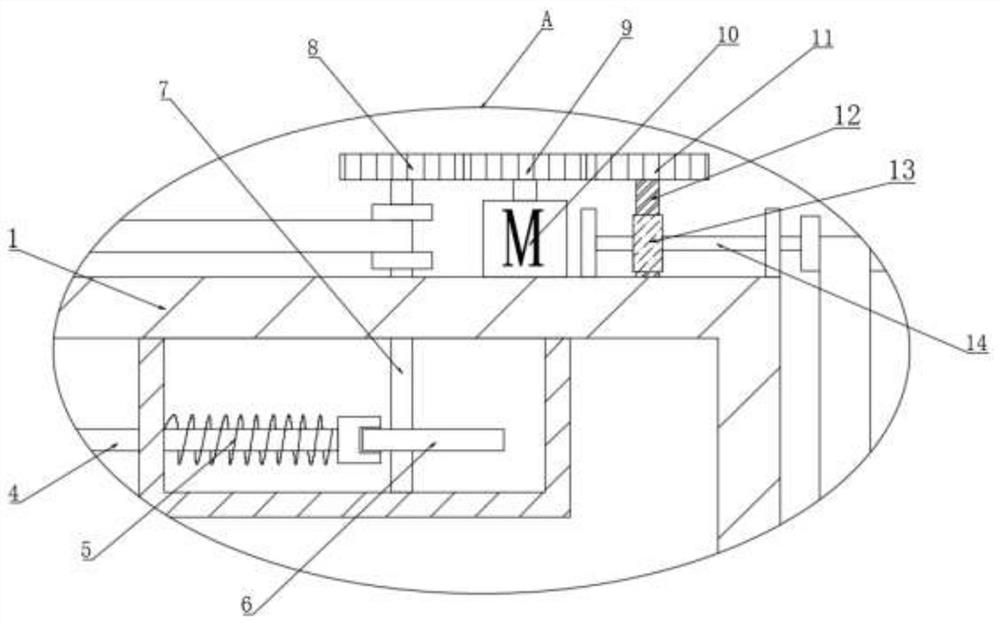
[0030] see Figure 1 to Figure 6, a sewage sludge separation treatment equipment, including a first treatment box 1, the top of the first treatment box 1 is provided with a feed port 2 for feeding, and the bottom of the feed port 2 is symmetrically provided with a The crushing tooth plate 3, the crushing tooth plate 3 is connected with a reciprocating drive assembly through a connecting rod 4, and the reciprocating drive assembly includes a first spring 5, a first cam 6, a first rotating shaft 7 and a first gear 8, the The first rotating shaft 7 is rotationally connected through a synchronous belt, and the first gear 8 is connected with a first rotary drive assembly through a second gear 9. The first rotary drive assembly includes a first motor 10, and the bottom of the crushing tooth plate 3 is An inverted V-shaped buffer plate is provided, and several crushing rollers 17 that are convenient for crushing are arranged under both sides of the inverted V-shaped buffer plate, and a

Embodiment 2

[0043] see Figure 1 to Figure 6 , a sewage sludge separation treatment equipment, including a first treatment box 1 and a second treatment box 37, also includes a second filter screen 27, the second filter screen 27 is provided with a material delivery assembly, the material delivery assembly Comprising a first material delivery shaft 24 and a second motor 25, the first material delivery shaft 24 is provided with material delivery blades, one side of the second filter screen 27 communicates with a second treatment box 37 through a pipeline, the A drying assembly is arranged in the second processing box 37, and the drying assembly includes a fifth rotating shaft 44, a blowing fan blade 45 and an electric heating wire 46. Three rotary drive assemblies, the third rotary drive assembly includes a fourth motor 38, a second worm 39 and a second worm wheel 40, the second worm wheel 40 is fixedly connected to the second stirring shaft 41, the second stirring shaft 41 is provided with a


PUM


Abstract

The invention discloses sewage and sludge separation treatment equipment, belongs to the technical field of sewage and sludge separation treatment, solves the problem of poor separation treatment effect of existing sewage and sludge treatment equipment. The equipment is technically characterized in that the equipment comprises a first treatment box, wherein sewage and sludge enter the first treatment box, a first motor is started, and reciprocating crushing of a crushing toothed plate is achieved, the crushing roller can perform the crushing again, a magnet can adsorb magnetic iron scraps, and a second cam rotates to achieve reciprocating vibration of a first filter screen; a third motor operates to achieve continuous rotation of stirring blades on a U-shaped stirring rod, the mixing effect is better, water is adsorbed and sterilized through a sterilization and odor suppression layer and a purification and disinfection layer, and discharging is convenient; sludge is placed in a second treatment box through material conveying blades on a first material conveying shaft, a fourth motor drives a crushing cutter on a second stirring shaft to crush, blowing fan blades rotate to generate wind which is blown to an electric heating wire for drying, the material conveying blades on a second material conveying shaft rotate to convey materials, and the sludge separation treatment device has the advantage of being good in separation treatment effect.

Description


Claims


Application Information

Patent Timeline
Owner 吴江市绿源环保科技有限公司
Why Eureka
Try Eureka