Double-half outer ring joint bearing

A joint bearing and semi-outer ring technology, applied in the field of bearings, can solve problems such as cracking, easy deformation of the bearing, weak bearing capacity of the outer ring, etc., and achieve the effect of convenient and quick disassembly

Inactive Publication Date: 2014-05-14
瓦房店福斯特轴承科技开发有限公司
View PDF0 Cites 6 Cited by
  • Summary
  • Abstract
  • Description
  • Claims
  • Application Information

AI Technical Summary

Benefits of technology

This new type of bearing has several benefits compared to traditional methods like riveting or welding. These advantages include ease of assembly, less damage caused by external forces during use, reduced weight for better performance, easier maintenance after installation, etc., which makes this design safer and reliable over time.

Problems solved by technology

This technical problem addressed by this patented design relates to improving the strength and durability of joints used for transmitting rotating motion between two parts that are difficultly assembled together due to their lacking support from other components during use.

Method used


Image

  • Double-half outer ring joint bearing
  • Double-half outer ring joint bearing

Examples


Embodiment Construction

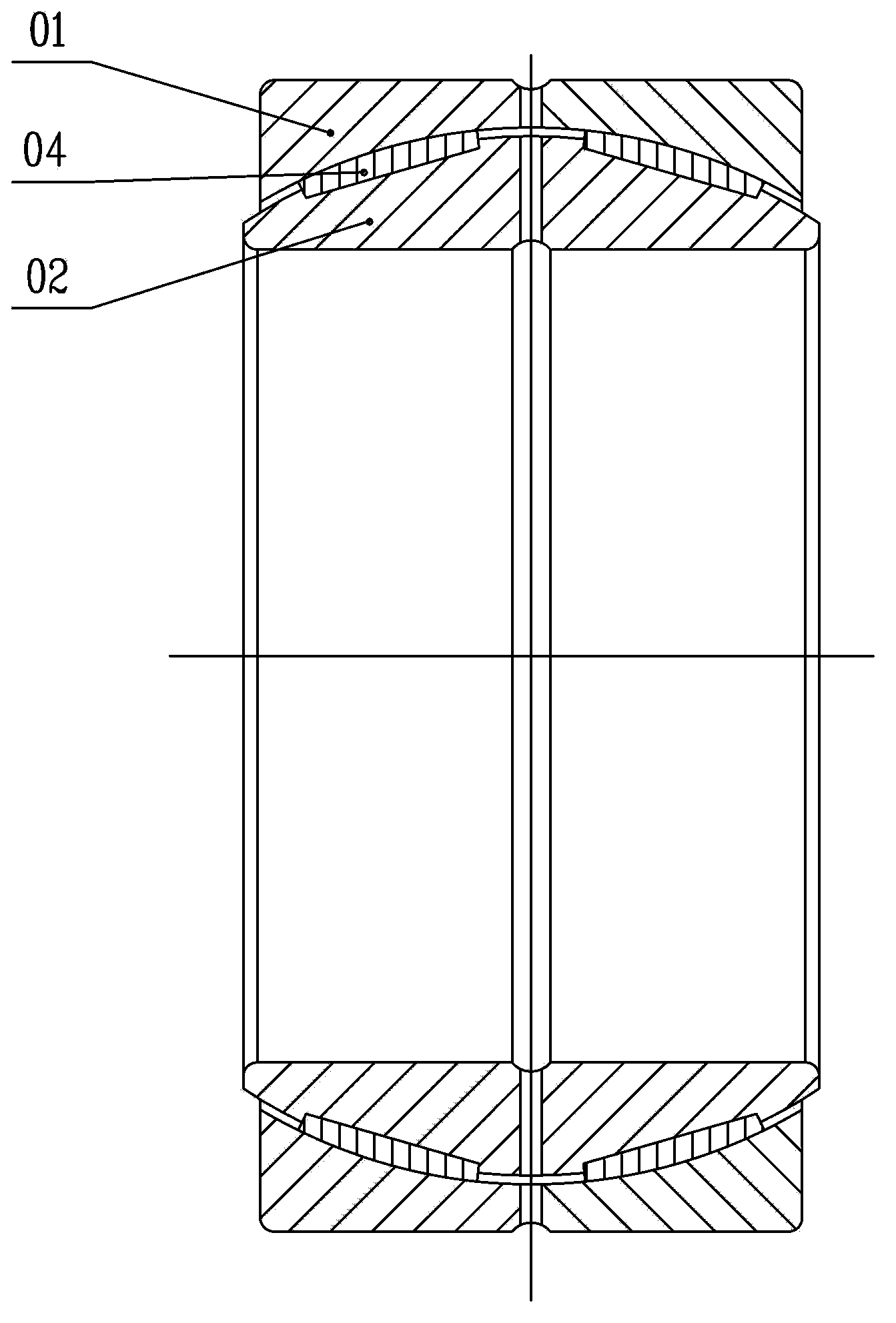
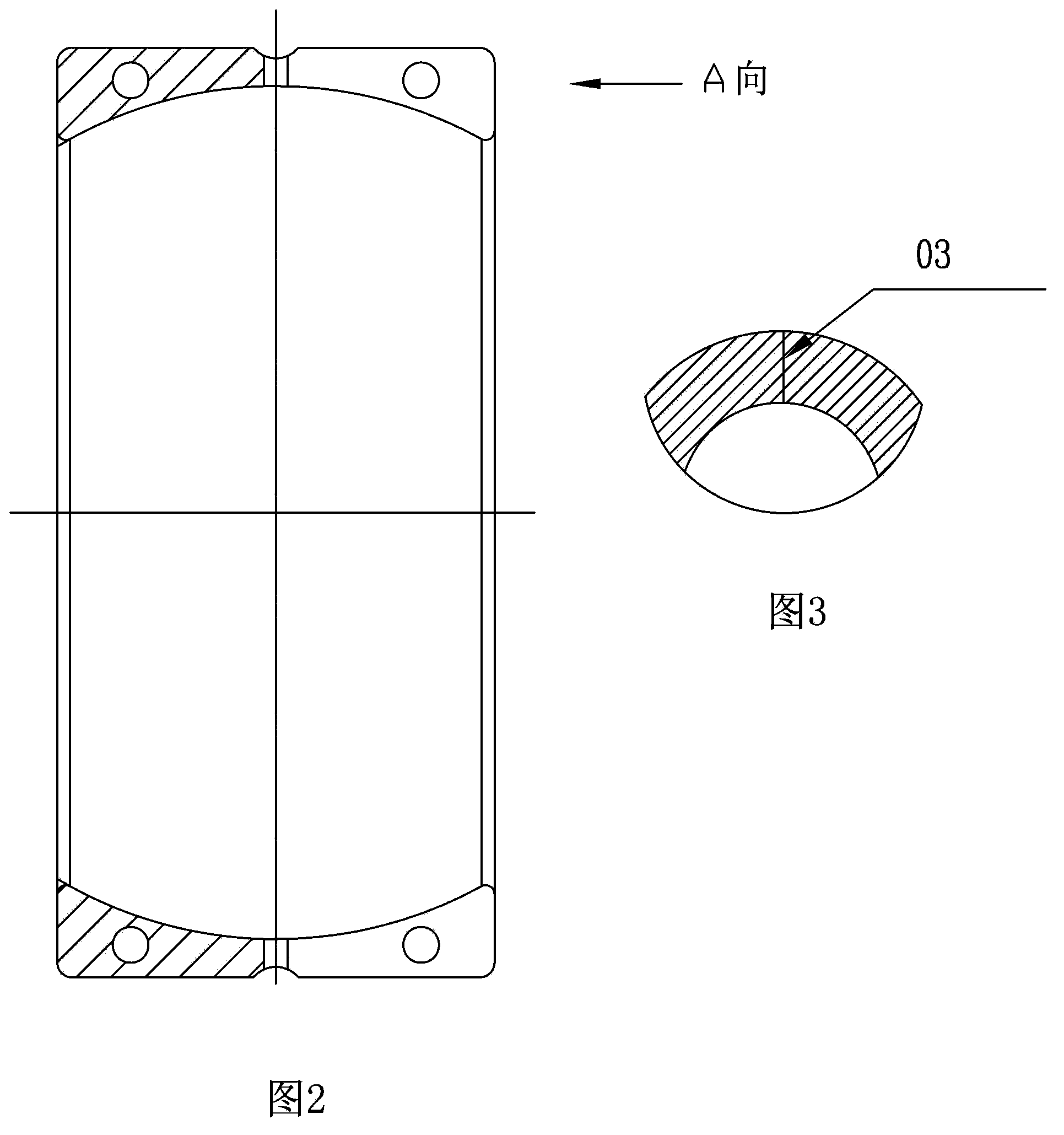
[0011] Such as Figure 1-3 The double half outer ring joint bearing shown includes the outer ring 01, the inner ring 02 and the inner block 04 between them. The present invention changes the previous single-cut press-in method of joint bearings, the outer ring is axially cut into two halves by wire cutting, and the inner ring is assembled on the outer ring during installation and the two halves are screwed together The outer rings are connected together. image 3 In the middle, the number 03 is the cutting point of the end face line (cut through).

[0012] The above are only preferred specific embodiments of the present invention, but the scope of protection of the present invention is not limited to this. Anyone familiar with the technical field within the technical scope disclosed in the present invention, according to the technical solution of the present invention Equivalent replacements or changes to its inventive concept should all fall within the protection scope of the pres


PUM


Abstract

The invention discloses a double-half outer ring joint bearing, which is characterized in that in a previous single-cutting pressed-in method, the joint bearing divides the outer ring into two parts through linear cutting along an axial direction, while installing, the inner ring is assembled to the outer ring, and two half outer rings are connected through a screw. The double-half outer ring joint bearing has the beneficial effects that 1) the bearing assembling method is more convenient and faster than the previous bearing dismounting method; and 2)on the aspect of a material, power bearing is not required when the double-half outer ring joint bearing is installed, two outer rings are connected through the screw. Previous bearing is pressed in the outer ring from the inner ring along the axial direction, so that the outer ring is expanded, and the deformation even fragmentation of the bearing is generated.

Description


Claims


Application Information

Patent Timeline
Owner 瓦房店福斯特轴承科技开发有限公司
Why Eureka
Try Eureka