Convenient faucet

A faucet and convenient technology, which is applied in the field of valve devices, can solve the problems of affecting the service life of the faucet, affecting the use effect, pushing the push handle, etc., and achieving the effects of avoiding disease transmission, stable water flow, and good sealing effect.

Active Publication Date: 2014-07-02
单祥海
View PDF7 Cites 2 Cited by
  • Summary
  • Abstract
  • Description
  • Claims
  • Application Information

AI Technical Summary

Problems solved by technology

When in use, because there is no sealing ring between the two ends of the rotating shaft and the wall of the water pipe, water will flow out from both ends of the rotating shaft when the water flow increases; after the faucet is turned on, because there

Method used


Image

  • Convenient faucet
  • Convenient faucet
  • Convenient faucet

Examples


Embodiment Construction

[0022] The present invention will be further described below according to the accompanying drawings and embodiments.

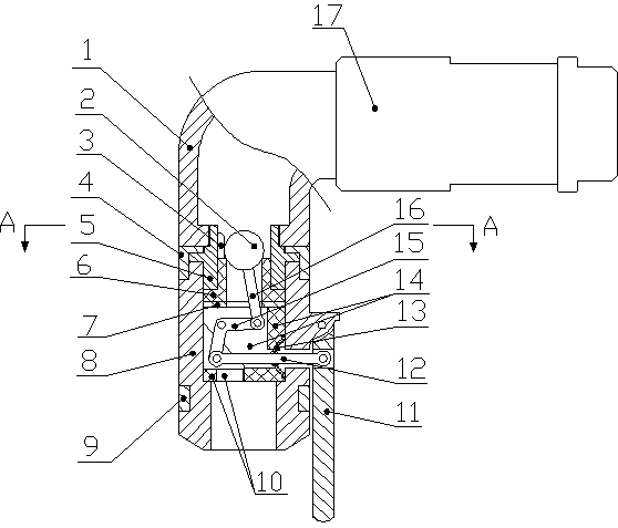
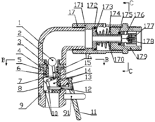
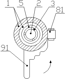
[0023] like Figure 1-Figure 4 A convenient faucet shown includes a housing, a spherical valve core 2 installed in the housing, a valve seat 6, a valve stem 16 whose upper end is connected to the valve core 2, and a push handle 11 installed outside the housing. The housing is divided into The water inlet pipe 1 and the water outlet pipe 8 are connected to each other; the lower end of the water inlet pipe 1 is connected with the water inlet joint 5, and the lower end of the water inlet joint 5 is connected with the water outlet pipe 8 and the retaining ring 4, and the water outlet pipe 8 is fixed on the water inlet joint 5 through the retaining ring 4 The lower end; the valve seat 6 is installed between the water inlet joint 5 and the water outlet pipe 8 . It is characterized in that: the upper end of the valve seat 6 is equipped with a limit sleeve 3 for limitin


PUM


Abstract

The invention discloses a convenient faucet which comprises a water inlet pipe, a water outlet pipe, a valve spool, a valve seat, a valve stem and a push handle. The water outlet pipe is disposed vertically, the water inlet pipe is connected with the water outlet pipe through a water inlet connector, and the other end of the water inlet pipe is connected with a pressure reducing valve. The valve seat is mounted between the water inlet connector and the water outlet pipe. A limit sleeve is mounted at the upper end of the valve seat, a support used for supporting a rotating arm is mounted below the valve seat, and a sealing element is fixed on the support. The middle of the rotating arm is hinged to the support through a hinge shaft, the upper end and the lower end of the rotating arm are hinged to the valve stem and a connecting rod respectively, and the connecting rod penetrates the support and the sealing element to be hinged to the push handle. The faucet is closed and opened by means of applying thrust to the push handle or removing the thrust, the effect that the faucet can be closed automatically after a user uses the faucet and leaves is achieved, the faucet is convenient and fast to use, and waste on water resources is reduced.

Description


Claims


Application Information

Patent Timeline
Owner 单祥海
Why Eureka
Try Eureka