Special high-strength and high-plasticity reinforcing steel bars for high speed railways
A high-speed railway, high-strength technology, applied in the field of high-strength steel bars, to achieve the effects of reducing loss force, uniform splitting force without direction, and high tensile strength
- Summary
- Abstract
- Description
- Claims
- Application Information
AI Technical Summary
Problems solved by technology
Method used
Image

Examples
Embodiment 1
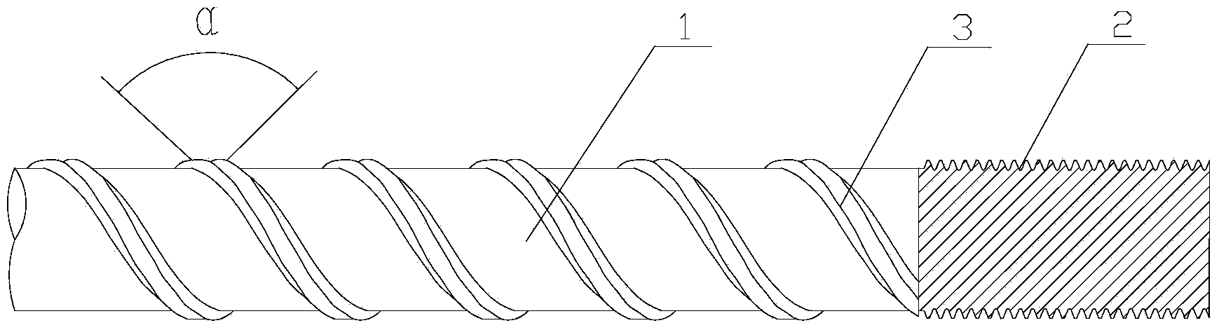
[0016] This embodiment proposes a special high-strength and high-plasticity steel bar for high-speed railways. The structure is as shown in 1. Each steel bar is 5m long and includes a steel bar body 1 and thread teeth 2 on the two ends of the steel bar body. A continuous spiral rib 3, the angle α formed by the two tangent lines between the two sides of the continuous spiral rib and the surface of the steel bar is 92°; the thread teeth are continuously distributed within 50mm of the end surface of the steel bar body, and the width of the thread teeth The width of the continuous spiral rib is 3mm and the height is 0.6mm.
[0017] The high-strength and high-plastic steel bars for high-speed railways in this embodiment comprise the following components by weight percentage: C: 0.35%, Si: 0.5%, Mn: 1.5%, Nb: 0.04%, Cr: 0.08%, V: 0.02%, B: 0.001%, Mo: 0.004%, Al: 0.01%, P: 0.02%, S: 0.015%, Ti: 0.0085%, Ni: 0.0035%, composite rare earth: 6%, and the balance is Fe and Other impurities,
Embodiment 2
[0023]This embodiment proposes a special high-strength and high-plasticity steel bar for high-speed railways. The structure is the same as that of Example 1. The difference lies in the components and processing methods of the high-strength and high-plasticity steel bars for high-speed railways in this embodiment. The steel in this embodiment is calculated by weight. The percentage contains the following components: C: 0.55%, Si: 0.9%, Mn: 1.7%, Nb: 0.05%, Cr: 0.09%, V: 0.04%, B: 0.003%, Mo: 0.007%, Al: 0.02% , P: 0.035%, S: 0.035%, Ti: 0.01%, Ni: 0.005%, compound rare earth: 7%, the balance is Fe and other impurities, and the compound rare earth contains the following components by weight percentage: La: 35% , Ce: 12%, Y: 9%, Sc: 14%, Gd: 3%, Sm: 6%, Dy: 2%, Pr: 19%.
[0024] The processing method of high-strength and high-plasticity steel bars for high-speed railways is carried out according to the following steps:
[0025] ⑴ Send the smelted steel bar into the heating furnace
Embodiment 3
[0029] This embodiment proposes a special high-strength and high-plasticity steel bar for high-speed railways. The structure is the same as that of Example 1. The difference lies in the components and processing methods of the high-strength and high-plasticity steel bars for high-speed railways in this embodiment. The steel in this embodiment is calculated by weight. The percentage contains the following components: C: 0.35%, Si: 0.5%, Mn: 1.5%, Nb: 0.04%, Cr: 0.08%, V: 0.02%, B: 0.001%, Mo: 0.004%, Al: 0.01%%, P: 0.02%, S: 0.015%, Ti: 0.0085%, Ni: 0.0035%, compound rare earth: 6%, the balance is Fe and other impurities, and the compound rare earth contains the following components by weight percentage: La : 33%, Ce: 11%, Y: 10%, Sc: 15%, Gd: 5%, Sm: 7%, Dy: 2%, Pr: 17%.
[0030] The processing method of high-strength and high-plasticity steel bars for high-speed railways is carried out according to the following steps:
[0031] ⑴ Send the smelted steel bar into the heating furn
PUM
| Property | Measurement | Unit |
|---|---|---|
| Tensile strength | aaaaa | aaaaa |
| Yield strength | aaaaa | aaaaa |
Abstract
Description
Claims
Application Information
 - R&D Engineer
- R&D Manager
- IP Professional
- Industry Leading Data Capabilities
- Powerful AI technology
- Patent DNA Extraction
Browse by: Latest US Patents, China's latest patents, Technical Efficacy Thesaurus, Application Domain, Technology Topic.
© 2024 PatSnap. All rights reserved.Legal|Privacy policy|Modern Slavery Act Transparency Statement|Sitemap