Friction cycle ergometer

Inactive Publication Date: 2014-09-10
BEIJING SPORT UNIV
View PDF6 Cites 1 Cited by
  • Summary
  • Abstract
  • Description
  • Claims
  • Application Information

AI Technical Summary

Benefits of technology

Problems solved by technology

This patented technical problem addressed by this patents relates to improving athletic performance through understanding factors like heartbeating capacity or muscle strength that may affect agility later onset (early after training). Existing devices only provide limited data about these variables but cannot accurately measure them due to lack of support tests programmes and insufficient measurement techniques.

Method used


Image

  • Friction cycle ergometer
  • Friction cycle ergometer
  • Friction cycle ergometer

Examples


Embodiment Construction

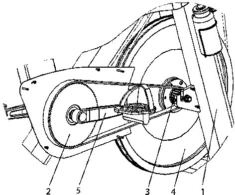
[0030] The invention discloses a friction power car, such as figure 1 As shown, a vehicle frame 1 is included, and a driving wheel 2, a driven wheel 3, a friction load wheel 4 and a pedal 5 are installed on the vehicle frame, and the pedal is relatively fixed coaxially with the driving wheel, and the driving wheel The driven wheel and the driven wheel are large and small synchronous pulleys respectively, and the number of teeth can be 84 and 22 respectively, and a synchronous belt transmission is adopted between the two, and the driven wheel and the friction load wheel are coaxially relatively fixedly installed. The pedal of the pedal is provided with a fixing belt, which is convenient for fixing the feet. During use, a person pedals on the pedal 5 to perform a riding action, the driving wheel rotates, and the driven wheel is driven to rotate through the belt transmission, thereby driving the friction load wheel to rotate synchronously with the driven wheel. Compared with the ch


PUM


Abstract

The invention relates to a friction cycle ergometer comprising a frame, a driving wheel, a driven wheel, a friction load wheel, pedals, a handlebar, a saddle, and a loading device. The pedal and the driving wheel are coaxially fixed; the driving wheel and the driven wheel are a large synchronous pulley and a small synchronous pulley respectively; the driving wheel and the driven wheel are driven via a synchronous belt; the driven wheel and the friction load wheel are coaxially and correspondingly fixed; the loading device comprises a friction rope, a transition wheel and a counterweight unit; the friction rope surrounding the friction load wheel and the transition wheel is tensioned; the friction rope is wound on the transition wheel by one to third cycles; the upper end of the counterweight unit is fixedly connected to the surface of the transition wheel, and the lower end of the counterweight unit is suspended. The friction cycle ergometer has the advantages that test data is reliable and accurate, the friction cycle ergometer can be used with various test schemes and fitness load schemes, the friction cycle ergometer can have multiple purposes, and the friction cycle ergometer can serve as an effective tool for the accurate evaluation of aerobic working capacity, the early discovery of sports risk and the guidance for scientific fitness.

Description


Claims


Application Information

Patent Timeline
Owner BEIJING SPORT UNIV
Why Eureka
Try Eureka