Two-roll tandem pipe mill and roll framework locking device thereof

A technology of locking device and roll mill, which is applied in the direction of metal rolling stand, metal rolling mill stand, metal rolling, etc., can solve the problems that the rolling balance of the roll stand cannot be guaranteed, and achieve the goal of overcoming the problem of rolling balance, The effect of flexible layout and simple structure

Active Publication Date: 2012-07-11
TAIYUAN HEAVY IND
View PDF7 Cites 9 Cited by
  • Summary
  • Abstract
  • Description
  • Claims
  • Application Information

AI Technical Summary

Problems solved by technology

[0007] Aiming at the problems existing in the prior art, the object of the present invention is to provide a roll stand locking device for a two-roll continuous pipe mill to overcome the sin

Method used


Image

  • Two-roll tandem pipe mill and roll framework locking device thereof
  • Two-roll tandem pipe mill and roll framework locking device thereof
  • Two-roll tandem pipe mill and roll framework locking device thereof

Examples


Embodiment Construction

[0017] Typical embodiments embodying the features and advantages of the present invention will be described in detail in the following description. It should be understood that the present invention is capable of various changes in different embodiments without departing from the scope of the present invention, and that the description and drawings therein are illustrative in nature and not limiting. this invention.

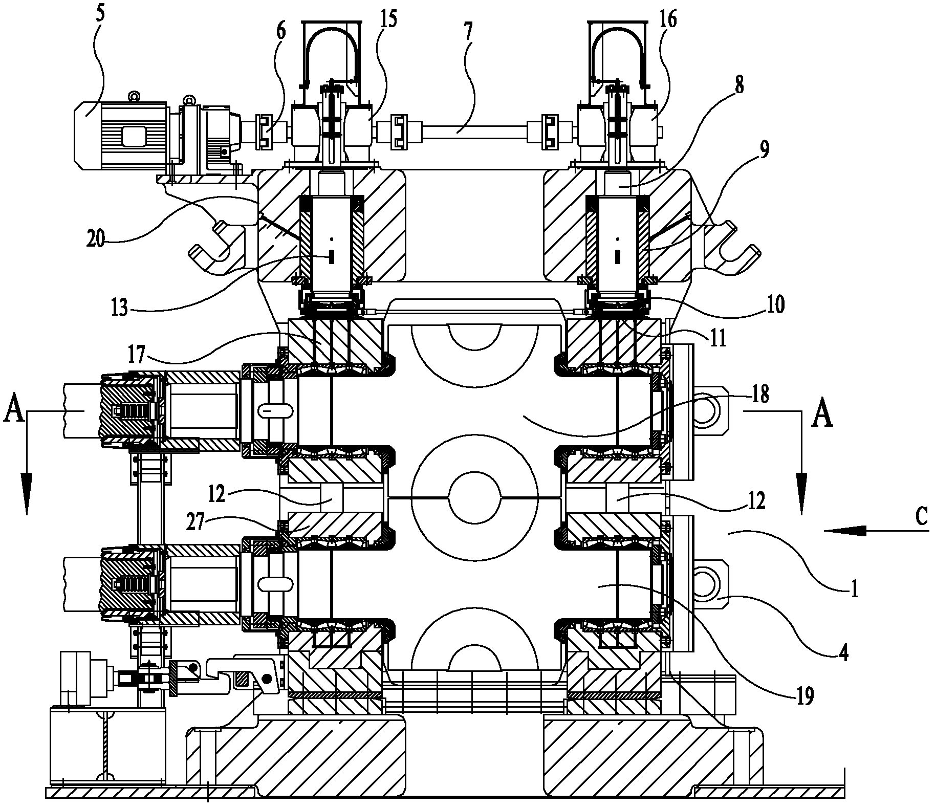
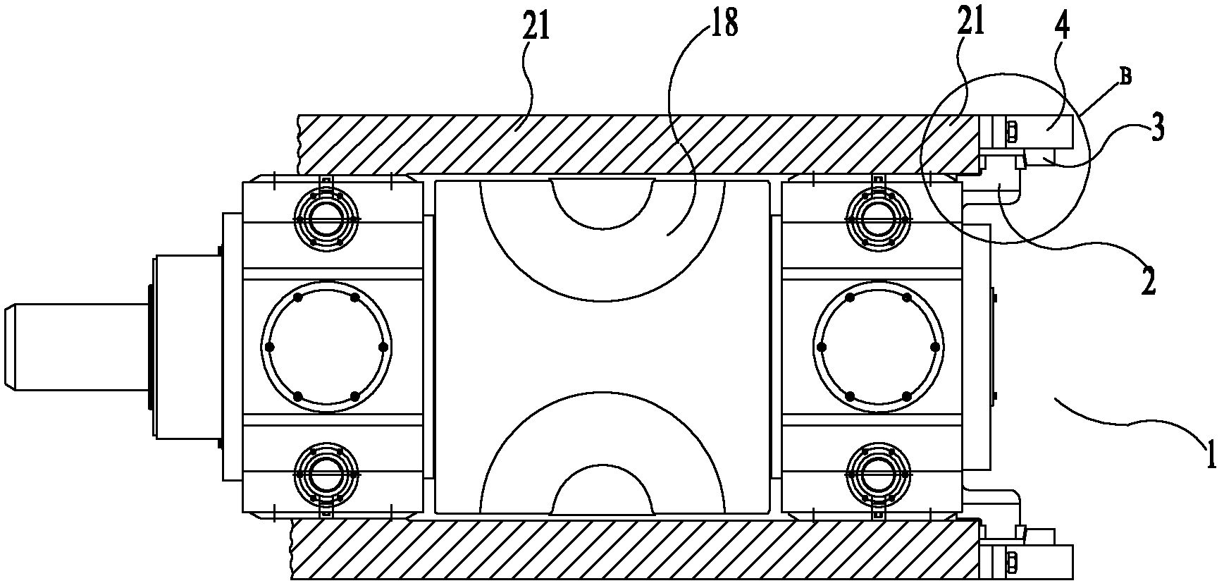
[0018] The roll stand locking device of the embodiment of the present invention is used in a two-roll continuous pipe rolling mill. The two-roll continuous pipe rolling mill of the embodiment of the present invention has the rolling stand locking device of the embodiment of the present invention.

[0019] The roll stand locking device of the embodiment of the present invention will be described in detail below.

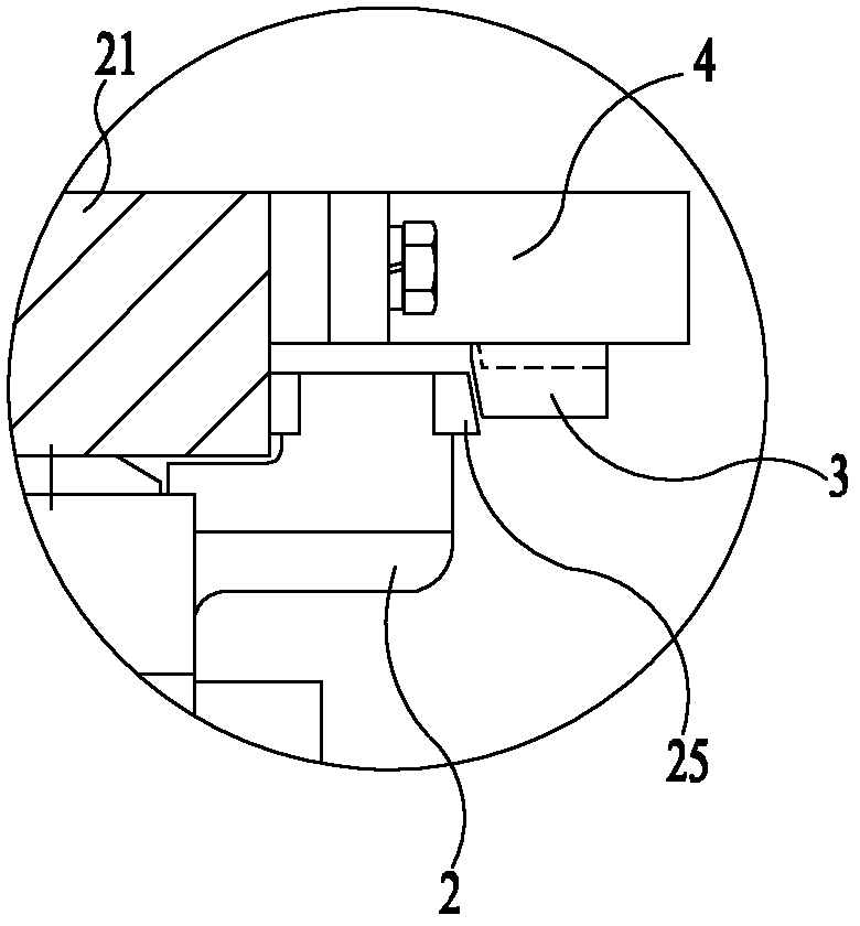
[0020] The working principle of the roll stand locking device in the embodiment of the present invention is to use a vertical pressing pressing device an


PUM

PropertyMeasurementUnit
Slopeaaaaaaaaaa

Abstract

The invention discloses a two-roll tandem pipe mill and a roll framework locking device thereof. The roll framework locking device comprises a pressing device and a side locking device. Rolls of the roll framework include a first roll and a second roll parallel to each other. After the roll framework is mounted into a main base, the side locking device is used for longitudinally locking the rolls of the roll framework, and the pressing device is used for pressing from the first roll to the second roll of the roll framework. The side locking device comprises a locking cylinder and a pressure-bearing backing plate, wherein the locking cylinder is arranged at the back end of the main base, and an extending end of the locking cylinder is a locking press head, a first bevel is formed on the locking press head, and a second bevel matched with the first bevel to lock the rolls longitudinally is formed on the pressure-bearing backing plate arranged at the back end of the roll framework. By the roll framework locking device, the problem of keeping horizontal rolling balance of the roll framework of the two-roll tandem pipe mill in the prior art is solved, stability of the roll framework in rolling is guaranteed effectively, and steel pipe rolling quality is improved further.

Description


Claims


Application Information

Patent Timeline
Owner TAIYUAN HEAVY IND
Why Eureka
Try Eureka