Clamping encapsulation structure for arc barriers

A technology of encapsulation structure and arc barrier, which is applied in the direction of circuit breaker components, etc., can solve the problems of weak arc extinguishing ability and complicated manufacturing process, and achieve the effect of enhancing arc extinguishing ability

Active Publication Date: 2014-09-24
BOER YIXING POWER SYST
View PDF5 Cites 1 Cited by
  • Summary
  • Abstract
  • Description
  • Claims
  • Application Information

AI Technical Summary

Benefits of technology

This patented design includes two parts: one has internal partitions for holding certain things like rails or other components inside while another part uses external ones made up from them. These partitions have slots on their edges matching the shape of the rail's surface. They fit tightly together during assembly without any gaps between them even if they were accidentally left open by someout-up force applied through gravity. Additionally, there may exist multiple ways to connect these partitions to create different shapes such as circular rings or rectangular plates. Overall, this design improves upon existing designs but still allows for efficient use of space within the fire extinction area.

Problems solved by technology

The technical problem addressed in this patented technology relates to making an improved design for current arc chutes that can perform both magnectically or pneumatically-fired flames without interferring with their functioning.

Method used


Image

  • Clamping encapsulation structure for arc barriers
  • Clamping encapsulation structure for arc barriers
  • Clamping encapsulation structure for arc barriers

Examples


Embodiment Construction

[0020] The present invention will be further described below in conjunction with the accompanying drawings and embodiments.

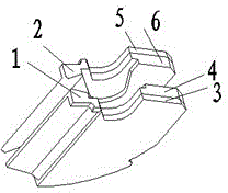
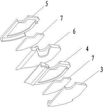
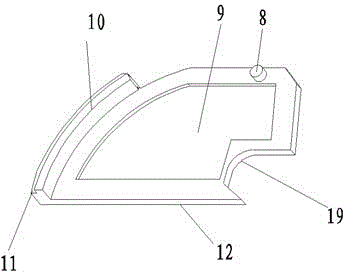
[0021] Please refer to figure 1 — Figure 5 As shown, the arc baffle clamping packaging structure of the present invention includes an upper arc baffle 1 and a lower arc baffle 2, and the upper arc baffle and the lower arc baffle are respectively provided with inner spacers 4, 6 and outer spacers 3, 5 and the magnetic-conducting part 7, the material of the inner spacer is a gas-producing material, and a groove 18 is provided to cooperate with the static contact, and a groove 15 for fastening with the magnetic-conductive part is reserved, the inner spacer, the outer The spacer embeds the magnetic guide parts in the preset grooves and fastens and clamps each other. When the arc is generated, the arc contacts the gas-generating materials of the left and right inner spacers, making it vaporize and generating gas containing hydrogen. This gas can cool the arc


PUM


Abstract

The invention provides a clamping encapsulation structure for arc barriers. The clamping encapsulation structure comprises an upper arc barrier and a lower arc barrier, wherein the upper arc barrier comprises an inner spacer, an outer spacer and a magnetic conductive iron; the lower arc barrier comprises an inner spacer, an outer spacer and a magnetic conductive iron; one side of each inner spacer is provided with a first groove matched with a fixed contact while the other side is provided with a second groove buckled with the corresponding magnetic conductive iron; one side of each outer spacer is provided with a third groove buckled with the corresponding magnetic conductive iron, the two magnetic conductive irons are respectively embedded in the second groove and the third groove to be matched and connected with the same in a clamping manner by the two sets of inner spacers and outer spacers, the first grooves of the upper arc barrier and the lower arc barrier are opposite to each other and matched and connected with the fixed contact in a clamping manner. According to the clamping encapsulation structure, the magnetic conductive irons are respectively arranged on the upper arc barrier and the lower arc barrier in a clamping manner, the magnetic conductive irons are magnetized simultaneously and endowed with magnetic conduction functions, thus generating driving forces for driving arc and achieving the purpose of improving arc extinguishing capability of an arc extinguishing system.

Description


Claims


Application Information

Patent Timeline
Owner BOER YIXING POWER SYST
Why Eureka
Try Eureka