Layout structure of current limiting switch

A technology of layout structure and current limiting switch, which is applied to the parts of the protection switch, the operation/release mechanism of the protection switch, the protection switch, etc. The effect of optimizing the structure layout

Pending Publication Date: 2022-05-06
SHANGHAI LIANGXIN ELECTRICAL
View PDF1 Cites 0 Cited by
  • Summary
  • Abstract
  • Description
  • Claims
  • Application Information

AI Technical Summary

Benefits of technology

This innovation improves on existing designs for prevention or control over electrical arcs by making it easier to manufacture without having separate components that can be easily damaged during installation. It also makes it simpler than previous methods while still providing effective protection against damage caused from high voltage electricity.

Problems solved by technology

Technological Problem: Current MOSFET (metal oxide semiconductors) type fuses have limitations such as being too small for effective use due to their size constraints or requiring external power sources like batteries that may be difficult to install on certain parts of the equipment without causing damage during installation. Additionally, there exist issues related to maintaining proper function when exposed to extreme conditions where they could fail if subjected to excessive force from accidentally hitting them while still operating properly.

Method used


Image

  • Layout structure of current limiting switch
  • Layout structure of current limiting switch
  • Layout structure of current limiting switch

Examples


Embodiment 1

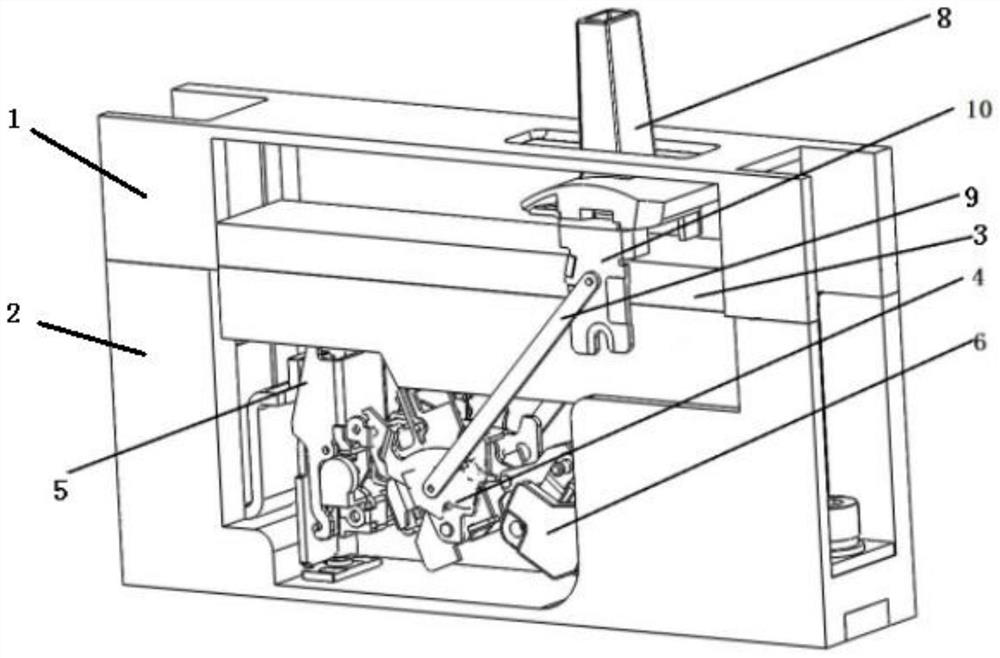
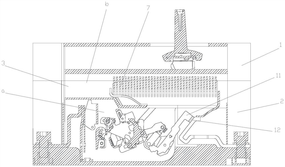
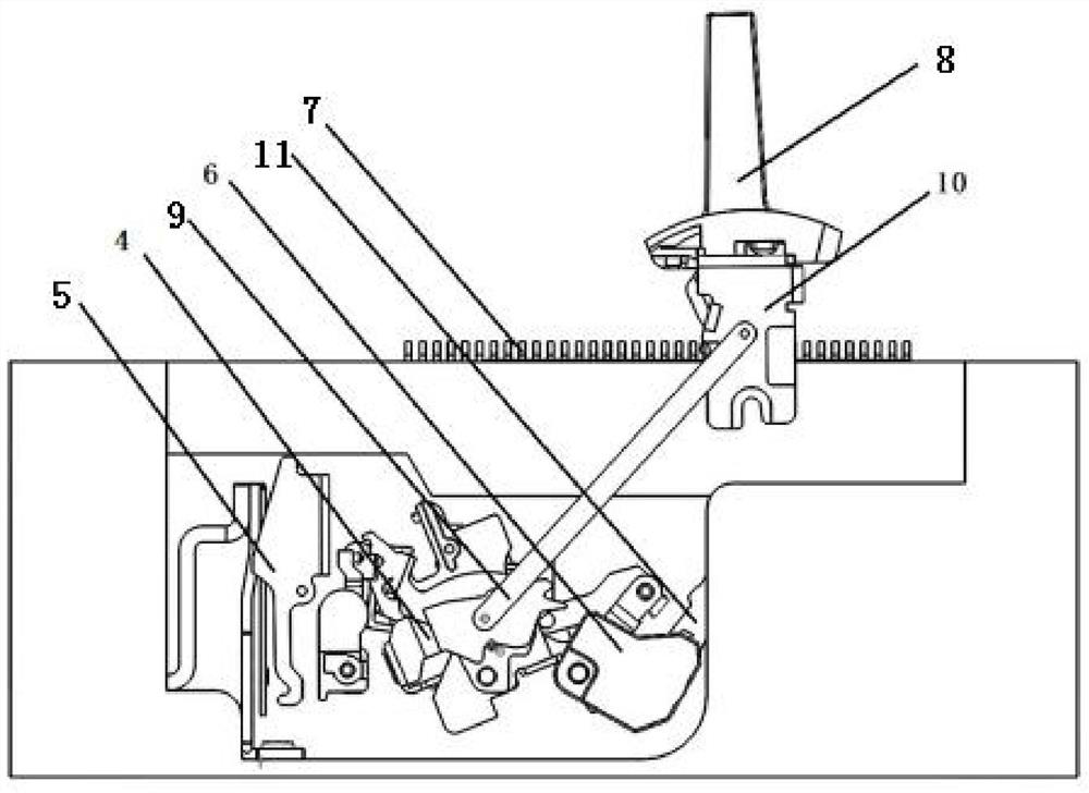
[0023] as attached figure 1 and 2 As shown, the layout structure of a current limiting switch provided by the present invention includes a middle cover 1 and a base 2, the middle cover 1 and the base 2 are assembled together in the up and down direction, and the base 2 is equipped with There is a chamber a, and the arc extinguishing system unit box 3 is located on the upper part of the chamber a, as attached image 3 As shown, in this embodiment, the arc extinguishing system unit box 3 is overlapped and fixedly installed on the upper part of the chamber a and can be disassembled independently, and the arc extinguishing system can occupy the entire base without increasing the overall appearance size of the product. The upper space of the cavity maximizes the capacity of the arc extinguishing chamber, and at the same time, it can elongate the arc and evenly enter the arc extinguishing chamber, so as to speed up the transfer speed of the arc.

[0024] as attached figure 1 And att


PUM


Abstract

The embodiment of the invention discloses a layout structure of a current limiting switch, which comprises a middle cover (1) and a base (2), and is characterized in that the middle cover (1) and the base (2) are mutually assembled together in the vertical direction, a cavity (a) is arranged in the base (2), an arc extinguishing system unit box (3) is positioned at the upper part of the cavity (a), and the arc extinguishing system unit box (3) is positioned at the lower part of the cavity (a). And the middle cover (1) and the arc extinguishing system unit box (3) are spliced up and down to form an arc extinguishing system chamber (b). By optimizing the structural layout of the circuit breaker, the tripper and the mechanism are arranged in the whole structure, and the mechanism and the tripper do not need to be independently coated with a shell in an insulating manner, so that the production process is simplified, and the shell assembly looseness is avoided.

Description


Claims


Application Information

Patent Timeline
Owner SHANGHAI LIANGXIN ELECTRICAL
Why Eureka
Try Eureka