Pulling force test clamp

A technology of tensile testing and fixtures, which is applied in the direction of measuring devices, instruments, scientific instruments, etc., can solve the problems of affecting work efficiency, difficult to guarantee the quality of wire harnesses, and can not be clamped, so as to improve accuracy, improve production efficiency, reduce The effect of labor intensity

Active Publication Date: 2014-10-01
HUIZHOU ZHUCHENG WIRING SYST
View PDF6 Cites 2 Cited by
  • Summary
  • Abstract
  • Description
  • Claims
  • Application Information

AI Technical Summary

Benefits of technology

This patented design allows for better control over how tightens or loosened wires can be tested by pulling them downward on an elastic body called a stretch-tester' s jaw (PT) instead of relying solely upon teeth patterns. By doing it securely, the PT has its own mechanism to hold back any loose parts during tests without being affected negatively affect their performance. Additionally, when used with a reversal process where one part goes deeper into another part, there will also reduce manual effort required while still ensuring accurate results. Overall, these technical improvements help make strengthening connections more reliable and efficient than current methods like riveting bolts.

Problems solved by technology

This patented technical problem addressed by this patents relates to improving the accuracy of measuring tension-strain resistance (TSI) for use with connectors that are commonly found at ends of electric cables. Existing methods require multiple steps involving tools like screwdrivers, pliers, etc., making them time-consuming and prone to errors during installation process. Therefore there needs a more efficient way to measure these properties accurately without requiring many different components.

Method used


Image

  • Pulling force test clamp
  • Pulling force test clamp
  • Pulling force test clamp

Examples


Embodiment Construction

[0019] In order to facilitate those skilled in the art to understand the technical content of the present invention, the present invention will be further described in detail below in conjunction with the accompanying drawings and embodiments.

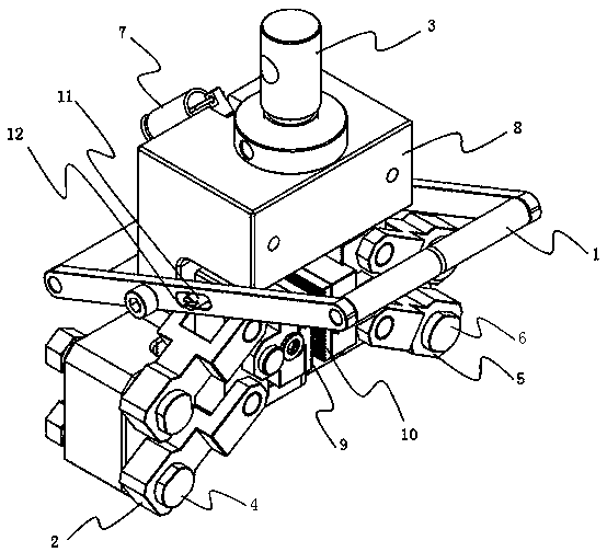
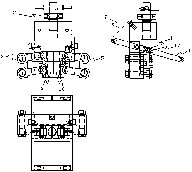
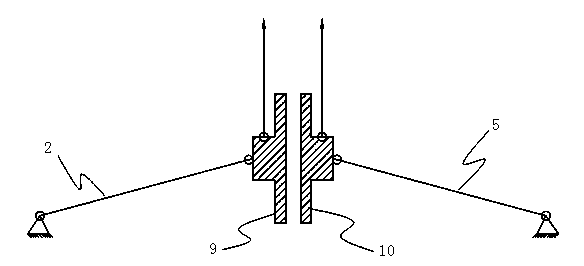
[0020] Such as figure 1 Shown is a wire harness pull test fixture, including a fixture body, a tie rod, a left moment arm, a right moment arm, a left clamp, and a right clamp. The pull rods are arranged at both ends of the clamp body through bolts, and the left moment arm and the right moment arm are arranged at the front side door of the fixture body through bolts, and the left moment arm and the right moment arm can respectively rotate in a fan-shaped area around the bolt axis. The left splint is connected to the left arm by bolts and the protrusion on the left splint is limited in the groove on the pull rod, the right splint is connected to the right arm by bolts and the protrusion on the right splint is limited to the groove on the ri


PUM


Abstract

The invention provides a pulling force test clamp, in particular to a wire harness pulling force test clamp. The pulling force test clamp comprises a clamp main body, a pulling rod as well as left force arms, right force arms, a fixing head, a return spring, fixing screws, a left clamp plate and a right clamp plate, wherein the fixing head is arranged at the top of the clamp, and is screwed with a punch pin; the return spring is arranged between the pulling rod and the clamp main body; the fixing screws are arranged to fix the left force arms and the right force arms; the left clamp plate and the right clamp plate are arranged on the left force arms and the right force arms. According to the invention, tooth threads are adopted on the clamping plates of the clamp to occlude; the pulling rod adopts a reversed technology to occlude the wire harness and the clamping plates together; the clamp plates clamp the wire harness tighter when the pulling force testing machine pulls higher; pulling force testing accuracy is improved greatly; meanwhile, the pulling rod is adopted to drive the force arms, so as to greatly relieve labor intensity of operating personnel, and improve production efficiency.

Description


Claims


Application Information

Patent Timeline
Owner HUIZHOU ZHUCHENG WIRING SYST
Why Eureka
Try Eureka