Rectification device for biodiesel purification

A biodiesel and rectification technology, used in biofuels, fat oil/fat refining, petroleum industry, etc., can solve the problems of limited heat exchange area, poor adaptability of raw materials, affecting heat exchange effect, etc., to increase the adhesion area and heating process. Long, good vaporization effect

Inactive Publication Date: 2014-10-08
CHENGDU HENGRUN HIGH NEW SCI & TECH
View PDF4 Cites 3 Cited by
  • Summary
  • Abstract
  • Description
  • Claims
  • Application Information

AI Technical Summary

Problems solved by technology

[0005] The multiple sets of heating trays in the above-mentioned distillation tower are arranged in a layered structure. When the fluid flows on it, separation will occur at the junction of adjacent heating trays, resulting in discontinuous heat exchange and affecting the heat exchange effect; at the same time, Each heating tray is a flat plate structure, and multi-layer heating trays are arranged in paralle

Method used


Image

  • Rectification device for biodiesel purification
  • Rectification device for biodiesel purification

Examples


Embodiment Construction

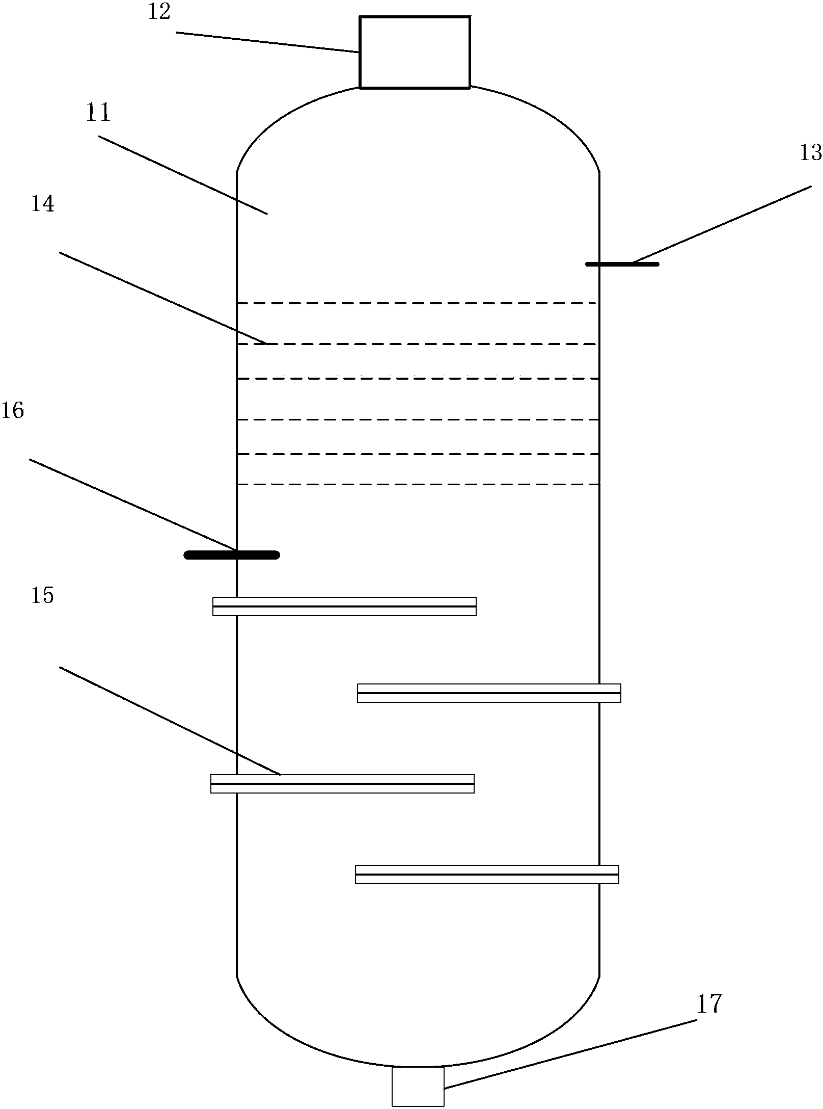
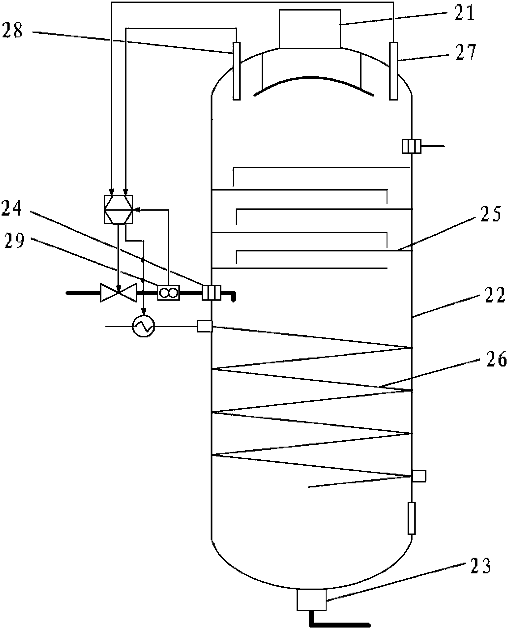
[0022] The core of the present invention is to provide a kind of rectification equipment for biodiesel purification, the heating plate is arranged in a spiral shape as a whole, so that the fluid in it will not be interrupted in heating when it flows on the heating plate, so that the heating process is relatively continuous, Therefore, the heat exchange effect is improved, the heat exchange efficiency is improved, and the performance of the rectification equipment is improved.

[0023] In order to enable those skilled in the art to better understand the solution of the present invention, the present invention will be further described in detail below in conjunction with the accompanying drawings and specific embodiments.

[0024] Please refer to figure 2 , figure 2 It is a structural schematic diagram of a specific embodiment of the rectification equipment provided by the present invention.

[0025] In a specific embodiment, the present invention provides a rectification devic


PUM


Abstract

The invention discloses a rectification device for biodiesel purification. The rectification device comprises a tower body, a vapor phase outlet, a raffinate outlet, a feeding inlet, baffling trays and heating plates. The vapor phase outlet is arranged on the top of the tower body, the raffinate outlet is arranged at the bottom of the tower body, the feeding inlet is arranged at the side wall of the tower body and is communicated with a raw material source with a crude biodiesel raw material, the baffling trays are arranged above the feeding inlet, the heating plates are arranged below the feeding inlet, the heating plates form a spiral structure and the spiral structure axially extends along a tower body axial direction. The heating plates form a spiral structure and heating stopping is avoided when flows flow on the heating plates so that the heating process is continuous, heat exchange effects are improved, heat exchange efficiency is improved, and rectification device performances are improved.

Description


Claims


Application Information

Patent Timeline
Owner CHENGDU HENGRUN HIGH NEW SCI & TECH
Why Eureka
Try Eureka