Process for converting a liquid feed material into a vapor phase product

a technology of liquid feed and product, which is applied in the direction of feed devices, hydrocarbon oil treatment, thermal non-catalytic cracking, etc., can solve the problems of liquid feed loss, increased mass and heat transfer rate, and other problems, to achieve the effect of high solids-to-oil ratio

Inactive Publication Date: 2012-08-23
ETX SYST
View PDF1 Cites 8 Cited by
  • Summary
  • Abstract
  • Description
  • Claims
  • Application Information

AI Technical Summary

Benefits of technology

The technical effect of this patented method is that it enables for efficient use of high solubility materials during production without requiring expensive equipment or excessive energy consumption.

Problems solved by technology

The technical problem discussed in this patent text relates to improving the efficiency of fluidized bed reactors during the production of high-quality liquid fuel. Specifically, the issue being solved is how to efficiently collect fine solid materials from the flow of the liquid mixture without causing damage to the equipment.

Method used


Image

  • Process for converting a liquid feed material into a vapor phase product
  • Process for converting a liquid feed material into a vapor phase product
  • Process for converting a liquid feed material into a vapor phase product

Examples


application case 1

12. Application Case 1—Application to the Upgrading of Heavy Oil

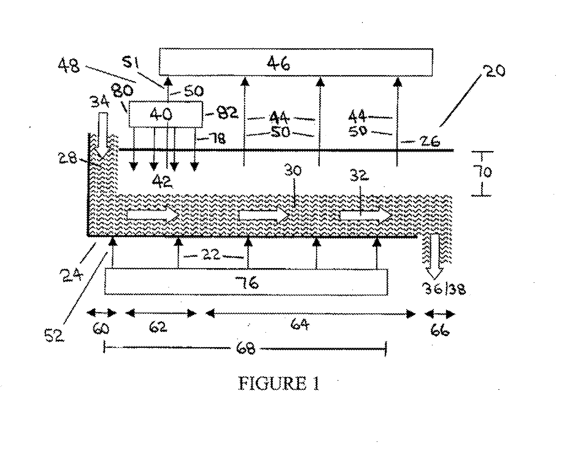
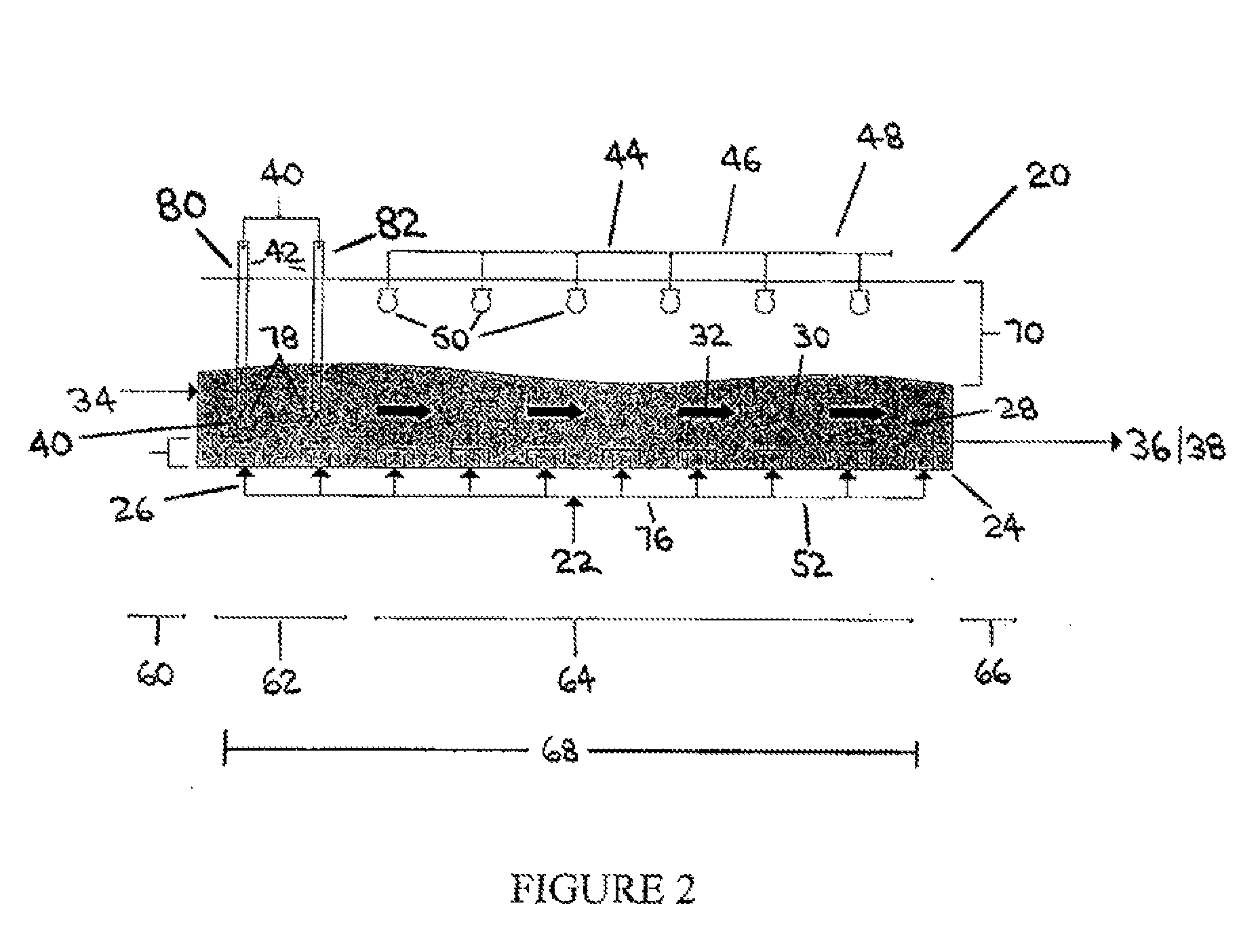
[0172]The following description describes a theoretical design of a specific application of the invention for the upgrading of a heavy oil, such as Athabasca bitumen. In this application, four reactor units are used in series (i.e. the solid particles (28) will flow from one reactor (20) into the next). Each unit has been designed to process feed at a rate of 250 bbl / day making the total capacity 1000 bbl / day. The design specifications and operating conditions for this application are listed in Table 1. The specifications listed in Table 1 are for a single reactor unit, and are based on an extensive piloting exercise designed for this purpose. The following is a brief explanation of the rationale behind the numbers in Table 1.

TABLE 1Operating Condition and Design Ranges for a Single Reactor UnitSpecific to Bitumen Where the Goal is to Maximize Liquid YieldSuitablePreferredOptimalReactor Length3 m-6 m4 m-5 m4.2mReactor


PUM


Abstract

A liquid feed material such as a heavy hydrocarbon feed in liquid form is contacted with a fluidized bed of heated solid particles which have a bulk horizontal velocity which is generally perpendicular to the flow of a fluidizing medium. The liquid feed material reacts on the solid particles to produce a vapor phase product, which vapor phase product is collected in a vapor collection apparatus.

Description


Claims


Application Information

Patent Timeline
Owner ETX SYST
Why Eureka
Try Eureka