Impact type particle separator made of mutually inverted U-shaped elements

a technology of u-shaped elements and particle separators, which is applied in the field of improved impact-type particle separator constructions, can solve the problems of limiting the length of collection elements of suitable alloys, and achieve the effects of reducing time and cost, preventing accidental disassembly during operation, and simplifying assembly and disassembly process

Inactive Publication Date: 2005-03-22
THE BABCOCK & WILCOX CO
View PDF13 Cites 0 Cited by
  • Summary
  • Abstract
  • Description
  • Claims
  • Application Information

AI Technical Summary

Benefits of technology

This patented technology makes it easier to install and maintain these types of separation devices by making them smaller than traditional methods like sand filters that require multiple workers' labor hours. Each device consists of separate parts attached onto an endless cooler pipe with no interference between others. These components are easy-to-lock into place when needed while still being effective at removing particles effectively.

Problems solved by technology

This patents describes an improvement on existing methods involving use of impacttype particle separation devices called collisional classifiers that work together with other components like baffle structures. However, current designs limit contact pressure performance compared to traditional design options based upon flat surface geometry principles. Additionally, there has also been research conducted showing how collision type particle sorting technology could improve energy utilization without reducing material quality.

Method used


Image

  • Impact type particle separator made of mutually inverted U-shaped elements
  • Impact type particle separator made of mutually inverted U-shaped elements
  • Impact type particle separator made of mutually inverted U-shaped elements

Examples


Embodiment Construction

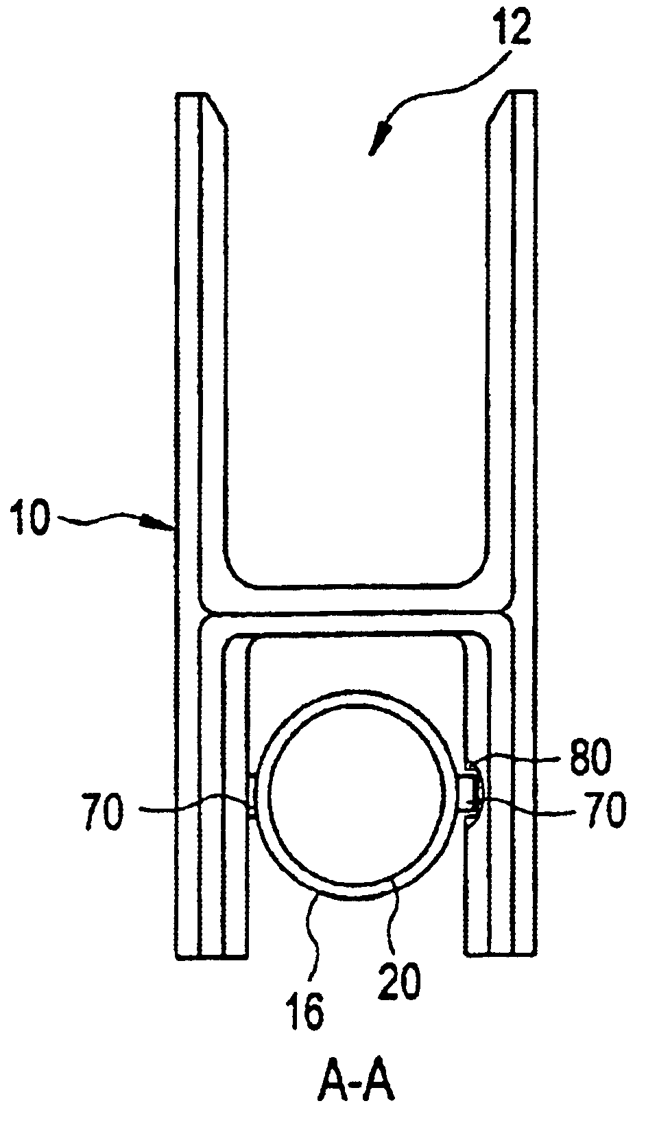
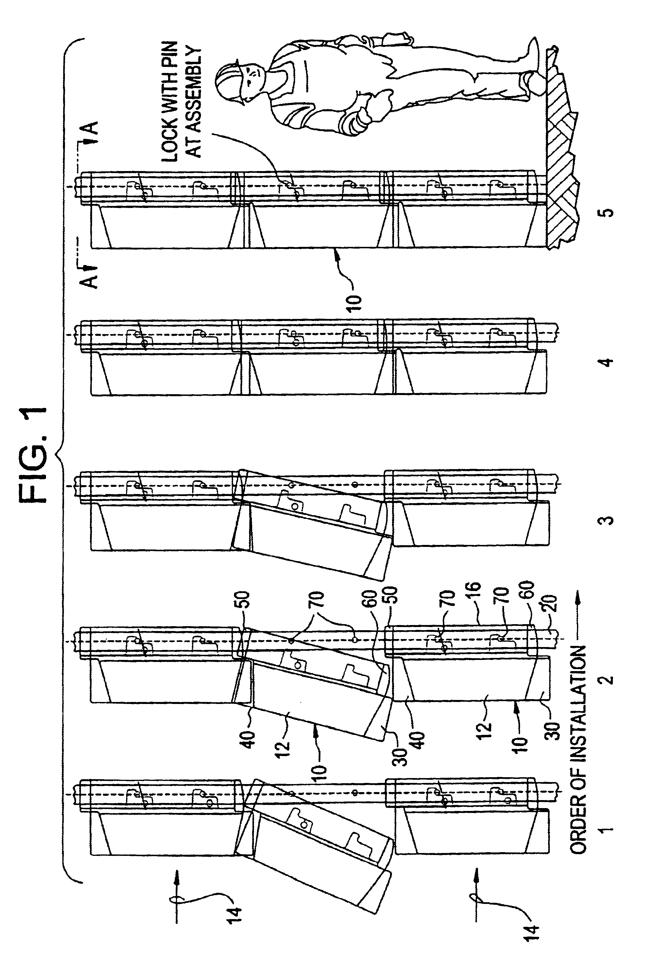
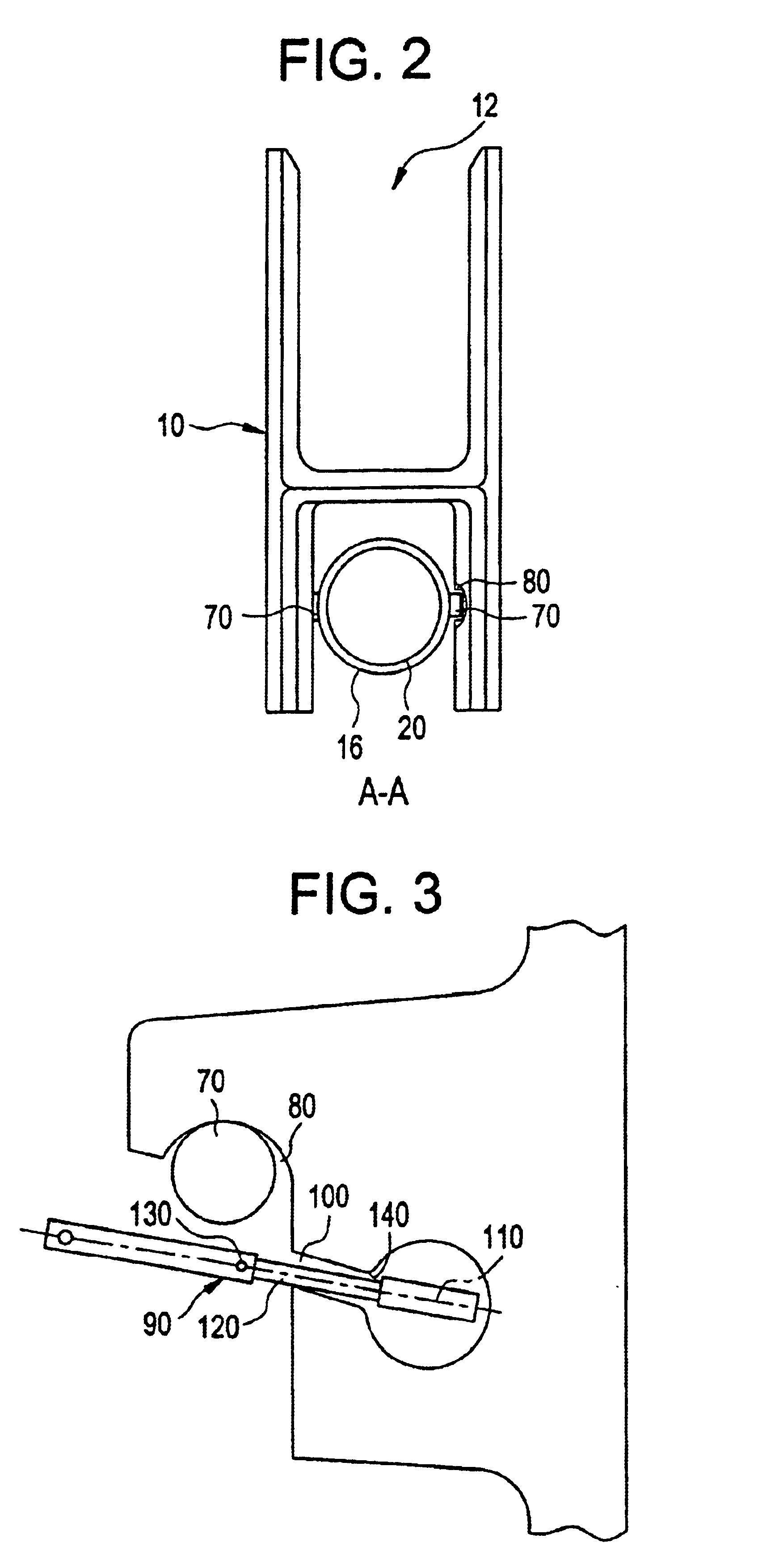
As used herein, the term CFB boiler will be used to refer to CFB reactors or combustors wherein a combustion process takes place. While the present invention is directed particularly to boilers or steam generators which employ CFB combustors as the means by which the heat is produced, it is understood that the present invention can readily be employed in a different kind of CFB reactor. For example, the invention could be applied in a reactor that is employed for chemical reactions other than a combustion process, or where a gas / solids mixture from a combustion process occurring elsewhere is provided to the reactor for further processing, or where the reactor merely provides an enclosure wherein particles or solids are entrained in a gas that is not necessarily a byproduct of a combustion process. Similarly, the term U-beam is used in the following discussion for the sake of convenience, and is meant to refer broadly to any type of concave impingement members or impact type particle


PUM

PropertyMeasurementUnit
Diameteraaaaaaaaaa

Abstract

Apparatus for separating solids from flue gas in a circulating fluidized bed (CFB) boiler comprises plural vertical, impact type particle separators made of a plurality of hung elements which are supported from at least one cooled support tube. The plurality of hung elements cooperate with one another at adjacent ends thereof to form a collecting channel which opens toward a flow of flue gas along the length of the support tube. Each hung element includes two mutually inverted U-shaped parts; the first U-shaped part opens towards the oncoming flow of flue gas, the second U-shaped part embraces the support tube, and the first U-shaped part is shifted relative to the second U-shaped part by some fraction of a height of the hung element. The hung elements may be made of metal or ceramic.

Description


Claims


Application Information

Patent Timeline
Owner THE BABCOCK & WILCOX CO
Why Eureka
Try Eureka