Integrated backflow-free A2O equipment based on fluidized bed

A non-reflux, fluidized bed technology, applied in chemical instruments and methods, multi-stage water treatment, water/sludge/sewage treatment, etc., can solve the problems of short hydraulic retention time, insufficient carbon source, high energy consumption, etc., to achieve The effect of reducing hydraulic concentration and dead zone, shortening the start-up period, and high volume utilization rate

Active Publication Date: 2021-05-11
SICHUAN UNIVERSITY OF SCIENCE AND ENGINEERING
View PDF10 Cites 0 Cited by
  • Summary
  • Abstract
  • Description
  • Claims
  • Application Information

AI Technical Summary

Problems solved by technology

[0003] The A2/O process is the simultaneous denitrification and phosphorus removal process (see Image 6 ), is a commonly used process in urban sewage treatment plants. It has the advantages of simple process composition, simple control, and not easy to produce sludge b

Method used


Image

  • Integrated backflow-free A2O equipment based on fluidized bed
  • Integrated backflow-free A2O equipment based on fluidized bed
  • Integrated backflow-free A2O equipment based on fluidized bed

Examples


Embodiment 1

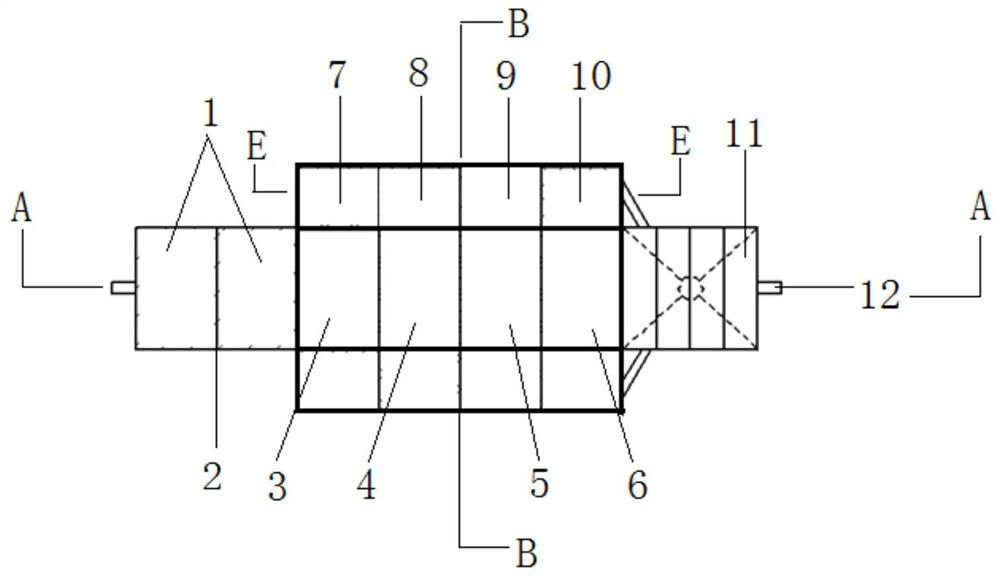
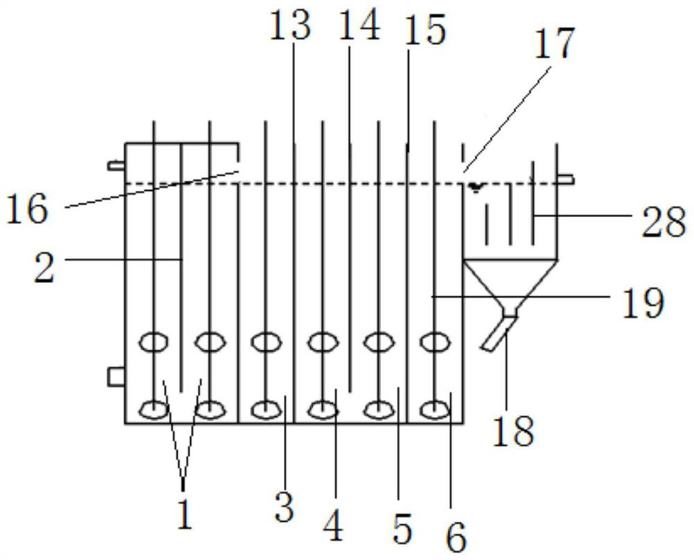
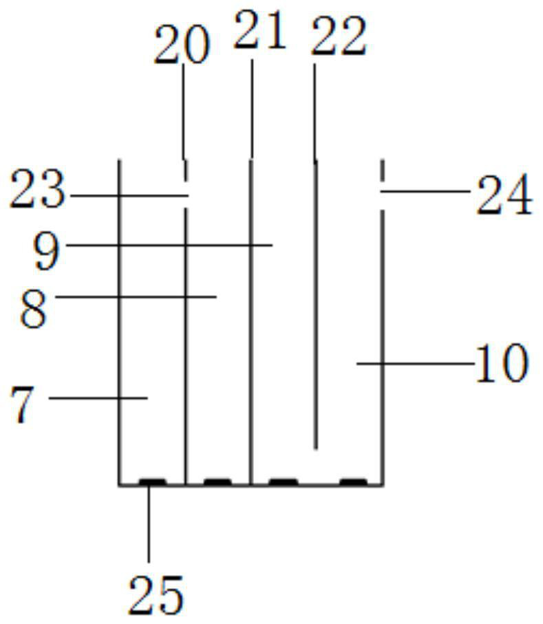
[0024] Embodiment 1: as Figure 1-Figure 6 as shown,

[0025] An integrated non-reflux A2O equipment based on fluidized bed, including anaerobic zone 1, anoxic zone, aerobic zone and sedimentation tank 11, anaerobic zone 1, anoxic zone and sedimentation tank 11 are set in sequence and pass through the overflow The aerobic zone is arranged on both sides of the anoxic zone and communicates with the anoxic zone and the sedimentation tank 11. The anoxic zone and the aerobic zone are separated by deflectors 26, and the deflectors 26 are arranged from top to bottom. At least two circulation ports 27; the bottom of the aerobic zone is provided with an aeration pan 25, the anaerobic zone 1 and the anoxic zone are provided with a stirring device 19; the bottom of the sedimentation tank 11 is provided with a sludge return port and a sludge discharge port 18, and the sludge The mud return port communicates with the anaerobic zone 1, and a water outlet 12 is set on the top of the side wall


PUM


Abstract

The invention provides integrated backflow-free A2O equipment based on a fluidized bed. The equipment comprises an anaerobic zone, an anoxic zone, aerobic zones and a sedimentation tank, and is characterized in that the anaerobic zone, the anoxic zone and the sedimentation tank are sequentially arranged and communicated through an overflow port, the aerobic zones are arranged on the two sides of the anoxic zone and communicated with the anoxic zone and the sedimentation tank, the anoxic zone and the aerobic zones are separated through flow guide plates, the flow guide plate is provided with at least two circulation ports from top to bottom, an aeration disc is arranged at the bottom of the aerobic zone, stirring devices are arranged in the anaerobic zone and the anoxic zone, the bottom of the sedimentation tank is provided with a sludge reflux inlet and a sludge discharge port, the sludge reflux inlet is communicated with the anaerobic zone, and the top end of the side wall of one side, far away from the anoxic zone, of the sedimentation tank is provided with a water outlet. According to the invention, efficient and low-energy-consumption wastewater treatment is realized.

Description


Claims


Application Information

Patent Timeline
Owner SICHUAN UNIVERSITY OF SCIENCE AND ENGINEERING
Why Eureka
Try Eureka