LED (light-emitting diode) lamp panel calibration system and method
A technology of LED light board and calibration method, applied in the direction of input/output to record carrier, instrument, static indicator, etc., can solve the problems of incorrect correction coefficient and inability to directly use the correction coefficient of light board.
- Summary
- Abstract
- Description
- Claims
- Application Information
AI Technical Summary
Problems solved by technology
Method used
Image

Examples
no. 1 example
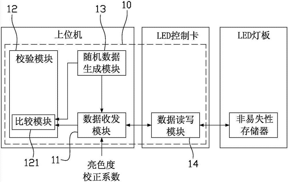
[0023] see figure 1 , which is a schematic diagram of the architecture of the LED lamp panel verification system according to the first embodiment of the present invention. like figure 1 As shown, the LED lamp panel verification system 10 of this embodiment is, for example, realized by the upper computer software installed on the upper computer and the lower computer software installed on the LED control card, wherein the upper computer is, for example, a personal computer system, and the LED control The card is, for example, the receiving card of the LED display synchronous control system containing programmable devices and / or embedded micro-processing or the asynchronous card of the LED display asynchronous control system, which can perform read and write control operations on the LED light board. Specifically, the LED lamp panel verification system 10 mainly includes: a data transceiving module 11 , a verification module 12 , a random data generating module 13 and a data r...
no. 2 example
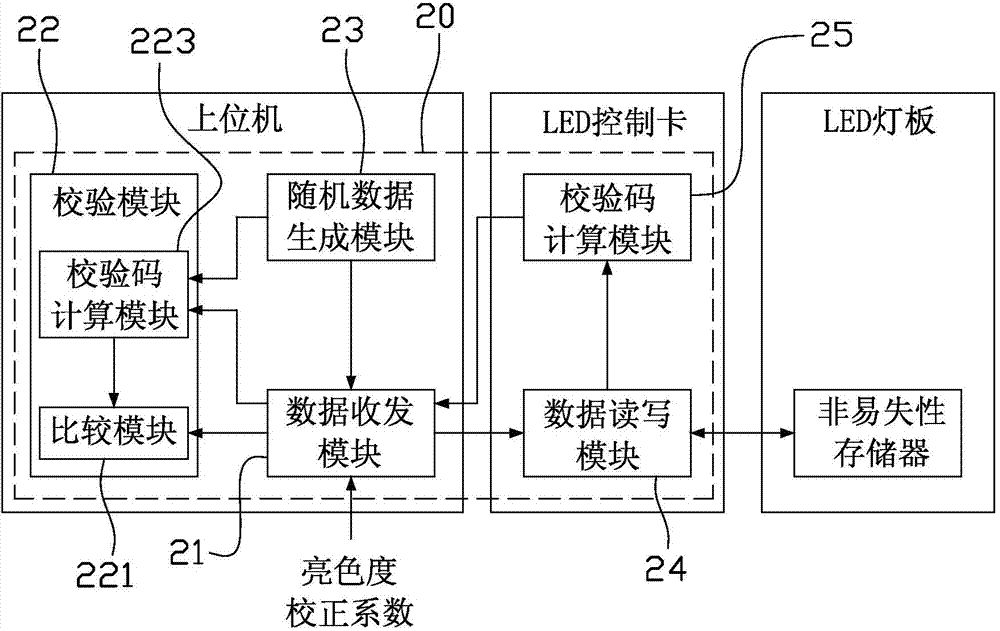
[0031] see figure 2 , which is a schematic diagram of the structure of the LED lamp panel verification system according to the second embodiment of the present invention. like figure 2 As shown, the LED lamp panel verification system 20 of this embodiment is, for example, jointly realized by the upper computer software installed on the upper computer and the lower computer software installed on the LED control card, wherein the upper computer is, for example, a personal computer system, and the LED control The card is, for example, the receiving card of the LED display synchronous control system containing programmable devices and / or embedded micro-processing or the asynchronous card of the LED display asynchronous control system, which can perform read and write control operations on the LED light board. Specifically, the LED lamp panel verification system 20 mainly includes: a data transceiving module 21 , a verification module 22 , a random data generation module 23 , a ...
no. 3 example
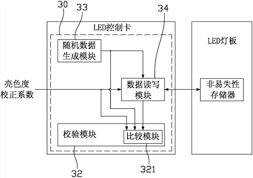
[0039] see image 3 , which is a schematic diagram of the structure of the LED lamp panel verification system according to the third embodiment of the present invention. like image 3 As shown, the LED lamp panel verification system 30 of this embodiment is realized, for example, by the lower computer software installed on the LED control card. The LED control card is, for example, the receiving card of the LED display synchronous control system containing programmable devices and / or embedded micro-processing or the asynchronous card of the LED display asynchronous control system, which can perform read and write control operations on the LED light board. Specifically, the LED lamp panel verification system 30 mainly includes: a verification module 32 , a random data generation module 33 and a data read-write module 34 , which are set on the LED control card; wherein, the verification module 32 includes a comparison module 321 .
[0040] The following will combine image 3 ...
PUM
 Abstract
Description
Claims
Application Information
 - R&D Engineer
- R&D Manager
- IP Professional
- Industry Leading Data Capabilities
- Powerful AI technology
- Patent DNA Extraction
Browse by: Latest US Patents, China's latest patents, Technical Efficacy Thesaurus, Application Domain, Technology Topic.
© 2024 PatSnap. All rights reserved.Legal|Privacy policy|Modern Slavery Act Transparency Statement|Sitemap