Online waste removing system for waste discharge area of plate type SCR denitration catalyst calcinator

A denitration catalyst and calciner technology, applied in the field of kiln auxiliary facilities, can solve the problems of excessive dust and volatile matter, difficulty in exhaust gas extraction, product quality defects, etc., and achieve the effect of avoiding secondary pollution

Inactive Publication Date: 2014-12-10
HUBEI DABIESHAN FURNACE IND RES & DESIGN INST
View PDF7 Cites 1 Cited by
  • Summary
  • Abstract
  • Description
  • Claims
  • Application Information

AI Technical Summary

Benefits of technology

This new technology allows for better control over how well fluids enter into the process during combustion processes by providing an improved way to install or remove filters that filter off impurities like ash particles while maintaining good thermal efficiency.

Problems solved by technology

Technological Problem: Current Denitrating Catalytic (SDC) Nozzle Ceramics® NOx Reduction Directive (NDR), including platy cerium oxide (PCA)-based catalyst systems, has been identified by various government regulators around the globe because they were found to cause air contaminations. However, there may also exist concerns over their use in other fields where strict regulation standards apply. To address these issues, technical problem addressed in this patented text involves developing efficient methods for producing large amounts of SDSCN catalyst without generating harmful substances like nitrosyl compounds called nobors.

Method used


Image

  • Online waste removing system for waste discharge area of plate type SCR denitration catalyst calcinator

Examples


Embodiment Construction

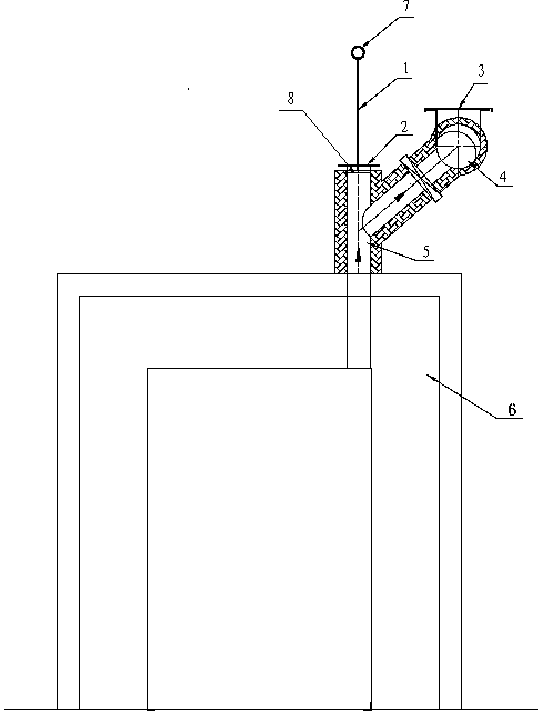
[0011] Such as figure 1 As shown, the online decontamination system for the waste area of ​​the calcination furnace of the plate type SCR denitrification catalyst is composed of a furnace body 6 in the waste area of ​​the calcination furnace, a vertical branch pipe 5 of the flue, a connecting branch pipe with a butterfly valve 4, a main exhaust pipe 3 and a fan. etc., the connection mode between the vertical branch pipe 5 of the flue and the connecting branch pipe where the butterfly valve 4 is set and the smoke exhaust main pipe 3 is a snap-fit ​​connection. The vertical branch pipe 5 of the flue is set on the top of the furnace body 6 in the waste area of ​​the calciner, and the smoke exhaust port on one side is connected to the main exhaust pipe 3 through the connecting branch pipe provided with the butterfly valve 4, and the top protrudes upwards to install a blind plate for installing a cleaner 2. Cleaner is made up of circular scraper 8, elevating rod 1 and handle 7, and c


PUM


Abstract

The invention discloses an online waste removing system for a waste discharge area of a plate type SCR denitration catalyst calcinator. The problems that in the prior art, dust and volatile matters in a calcinator are easily condensed and adsorbed to the inner wall of a gas flue, and product quality is affected are solved. The online waste removing system is characterized in that a gas flue vertical branch pipe (5) is arranged on the top of a body, in the waste discharge area, of the calcinator; a side flue gas discharge port is connected with a flue gas header pipe (3) through a connecting branch pipe provided with a butterfly valve (4); the top of the gas flue vertical branch pipe (5) extends upwards to form a blind plate provided with a waste removing device; the waste removing device is composed of a circular scraping plate (8), a lifting rod (1) and a handle (7); the circular scraping plate (8) is arranged in the gas flue vertical branch pipe (5), the center of the circular scraping plate (8) and the bottom of the lifting rod penetrating through the blind plate (2) are welded into a whole, and the top of the circular scraping plate (8) is provided with the handle (7). The online waste removing system has the advantages of being reasonable in structure, easy to operate, safe, environmentally friendly, efficient, high in quality and the like; waste adsorbed on a pipeline in production can be effectively removed in time, it is guaranteed that flue gas is pumped and discharged smoothly, the qualified rate of products are increased, and therefore the online waste removing system is worth popularizing.

Description


Claims


Application Information

Patent Timeline
Owner HUBEI DABIESHAN FURNACE IND RES & DESIGN INST
Why Eureka
Try Eureka