Explosion-proof and fire protection emergency mark lamp

A fire emergency and sign technology, applied in the field of explosion-proof fire emergency sign lamps

Active Publication Date: 2014-12-17
SHENZHEN OCEANS KING LIGHTING ENG CO LTD +1
View PDF4 Cites 6 Cited by
  • Summary
  • Abstract
  • Description
  • Claims
  • Application Information

AI Technical Summary

Problems solved by technology

[0004] Based on this, it is necessary to provide an explosion-proof fire emergency sign lamp tha

Method used


Image

  • Explosion-proof and fire protection emergency mark lamp
  • Explosion-proof and fire protection emergency mark lamp
  • Explosion-proof and fire protection emergency mark lamp

Examples


Embodiment Construction

[0023] The following will clearly and completely describe the technical solutions in the embodiments of the present invention with reference to the drawings in the embodiments of the present invention.

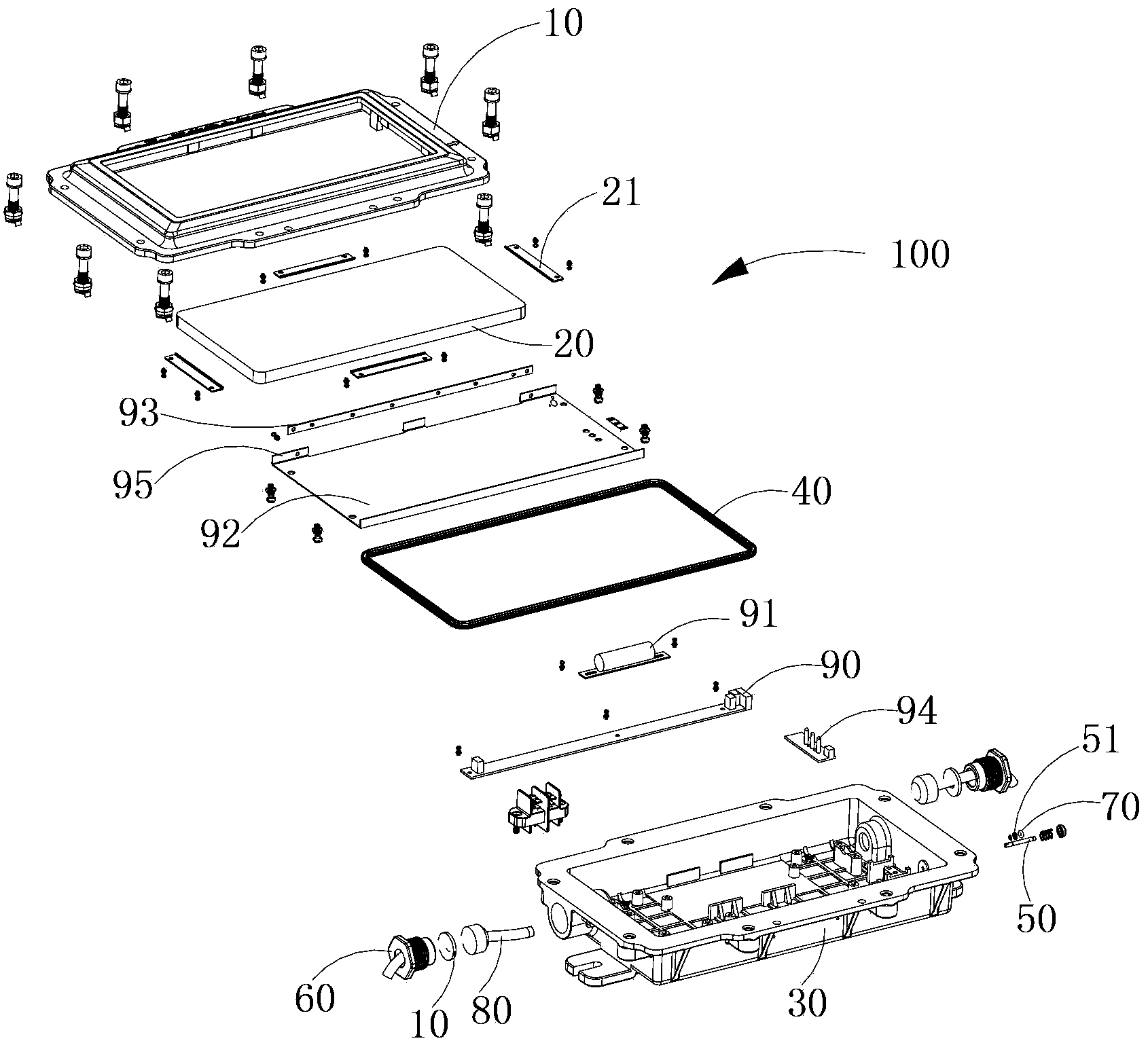
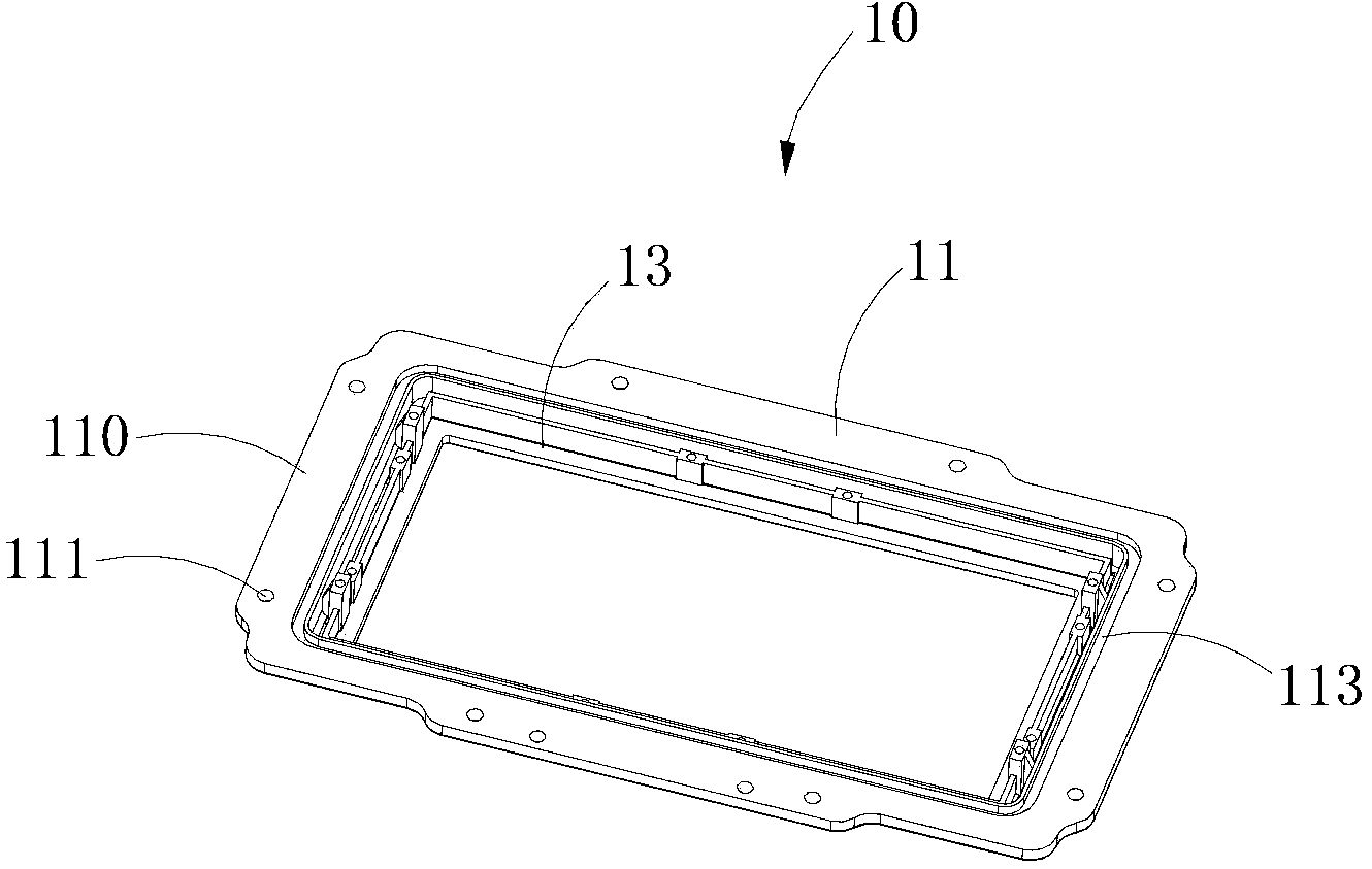
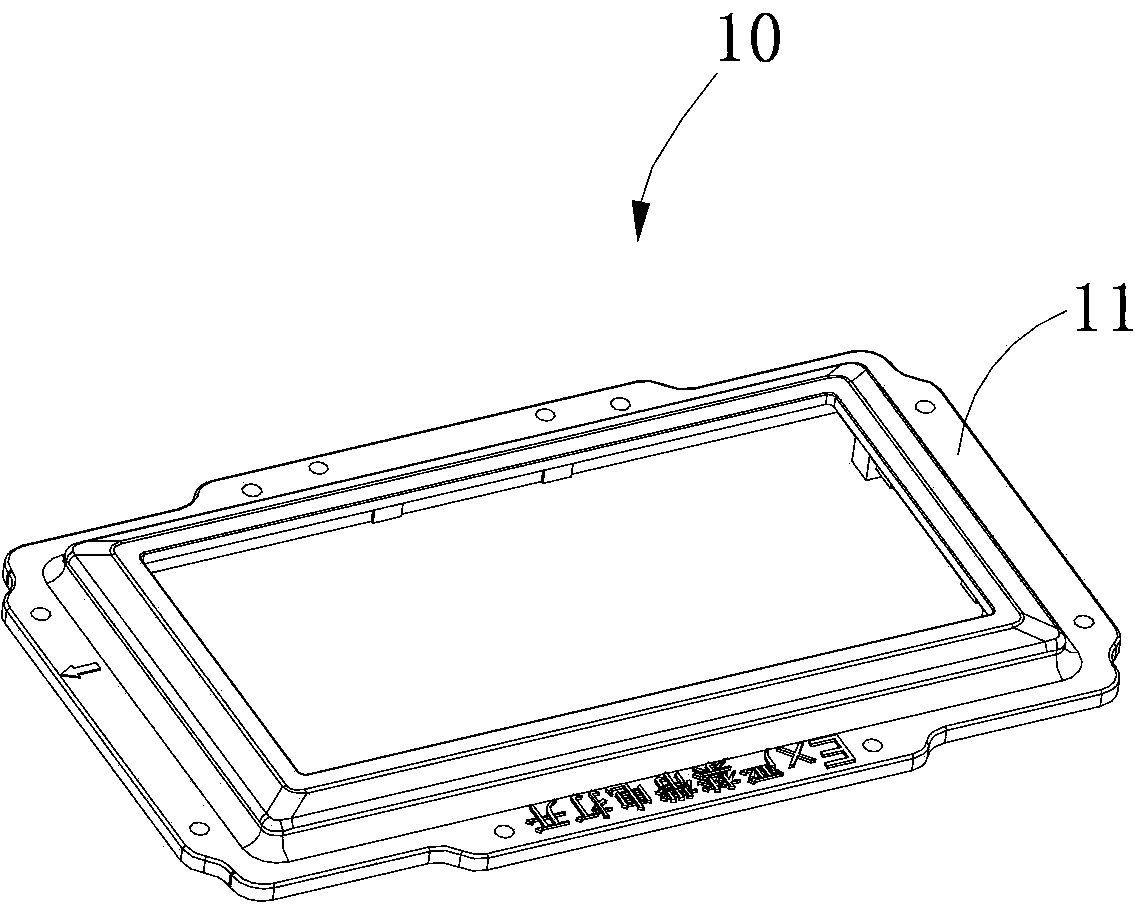
[0024] see figure 1 A preferred embodiment of the present invention provides an explosion-proof fire emergency sign lamp 100, which includes a face cover 10, an indicator transparent part 20 arranged on the face cover 10, a housing 30 matched with the face cover 10, and a cover 10 arranged on the face The sealing ring 40 at the joint between the cover 10 and the housing 30, the control rod 50 and the compression nut 60 arranged on the side wall of the housing 30, the O-ring 70 arranged at the joint between the control rod 50 and the housing 30, and The filler 80 is arranged at the joint between the compression nut 60 and the housing 30 . The joint surface of the face cover 10 and the housing 30 is a plane explosion-proof surface, the joint surface of the control rod 50 and the s


PUM


Abstract

The invention discloses an explosion-proof and fire protection emergency mark lamp. The explosion-proof and fire protection emergency mark lamp comprises a face cover, an indication mark transparent piece arranged on the face cover, a shell matched with the face cover, a sealing ring arranged at the matched position of the face cover and the shell, a control rod, a gland nut, an O-shaped sealing ring and padding arranged at the matched position of the gland nut and the shell, the control rod and the gland nut are arranged on the side wall of the shell, and the O-shaped sealing ring is arranged at the matched position of the control rod and the shell. The adjoining face of the face cover and the shell is a plane explosion-proof face. The adjoining face of the control rod and the side wall of the shell is a cylindrical explosion-proof face. The adjoining face of the gland nut and the side wall of the shell is a thread explosion-proof face. An independent and sealed explosion-proof cavity is formed by the face cover, the indication mark transparent piece, the shell, the sealing ring, the control rod, the O-shaped sealing ring, the gland nut and the padding. The explosion-proof and fire protection emergency mark lamp further comprises a reflector provided with a folded edge, and an LED light source plate is installed on the folded edge. The lamp can effectively solve the problem of the fire protection emergency line indication when a dangerous zone with the explosion-proof requirement is powered off, and the requirements for national fire protection safety and explosion-proof safety are met.

Description


Claims


Application Information

Patent Timeline
Owner SHENZHEN OCEANS KING LIGHTING ENG CO LTD
Why Eureka
Try Eureka