Injection molding machine

A technology of injection molding machine and cover plate, which is applied in the field of injection molding machines, can solve the problems of not reaching the theoretical height, troublesome injection molding production users, strength and quality not as good as ideal, etc., and achieve the effect of simple structure and low production cost

Inactive Publication Date: 2015-03-18
KUNSHAN JINHUAYUE MECHANICAL DESIGN
View PDF0 Cites 0 Cited by
  • Summary
  • Abstract
  • Description
  • Claims
  • Application Information

AI Technical Summary

Problems solved by technology

[0002] With the continuous promotion of the application of plastic products, the requirements for its quality are becoming more and more stringent, and the relative indicators of the strength and quality of plastic products are also getting higher and higher. For the traditional injection molding technology, its molding requires high The cos

Method used


Image

  • Injection molding machine

Examples


Embodiment Construction

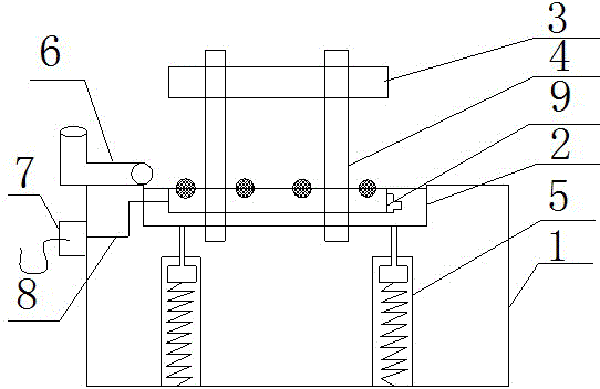
[0009] like figure 1 The shown injection molding machine includes an injection molding machine main body 1, a lower cover plate 2, an upper cover plate 3, a power connection port 7 and a wire 8, and a pressure pump 5 is fixed inside the injection molding machine main body 1. The pressure pump The top of 5 is fixed with a lower cover plate 2, the upper cover plate 3 and the lower cover plate 2 are connected by a fixing rod 4, the left end of the lower cover plate 2 is fixed with a feeding port 6, and the left end of the injection molding machine main body 1 is fixed. A power supply connection port 7 is provided on the side, and a fully automatic cleaning device 9 is fixed on the lower cover 2 , and the fully automatic cleaning device 9 is connected with the power supply connection port 7 through a wire 8 . The beneficial effects of the invention are that the structure is simple and the manufacturing cost is low.


PUM


Abstract

The invention relates to an injection molding machine, which comprises an injection molding machine main body, a lower cover plate, an upper cover plate, a power connector and a wire. Pressure pumps are fixed in the injection molding machine main body; the lower cover plate is fixed on the tops of the pressure pumps; the upper cover plate is connected with the lower cover plate through fixed rods; a feed port is fixed on the left end of the lower cover plate; the left side of the injection molding machine main body is provided with the power connector; an automatic cleaning device is fixed on the lower cover plate; and the automatic cleaning device is connected with the power connector through the wire. The invention has the beneficial effects of simple structure and low manufacture cost.

Description


Claims


Application Information

Patent Timeline
Owner KUNSHAN JINHUAYUE MECHANICAL DESIGN
Why Eureka
Try Eureka