Micro-molding injection molding machine

An injection molding machine and micro technology, applied in the field of new micro molding injection molding machines, can solve the problems of small quantity of medical plastic supplies, affecting treatment time, poor quality, etc., and achieve the effect of reducing procurement cost, saving operation area and simple structure

Inactive Publication Date: 2019-01-04
楼一
View PDF0 Cites 0 Cited by
  • Summary
  • Abstract
  • Description
  • Claims
  • Application Information

AI Technical Summary

Benefits of technology

This innovation allows for easy operation without complicated structures or bulky machinery that requires high maintenance costs. It achieves this through an improved design where it uses a compact mechanism to compress and move small objects like fused castings while maintain their shape during casting process. By connecting fluid pipes from different liquids together at one end, there will no longer be any obstacles when inserting them into other components such as valves or pumps due to pressure differences caused by gravity flow. Additionally, these new designs allow for easier handling and replacement of injectors used in manufacturing processes.

Problems solved by technology

This patented technical problem addressed by this patents relates to improving the supply chain for producing high-quality medical products such as microplastics without causing contamination or requiring expensive materials during replacements due to their low quantities produced at home.

Method used


Image

  • Micro-molding injection molding machine
  • Micro-molding injection molding machine
  • Micro-molding injection molding machine

Examples


Embodiment Construction

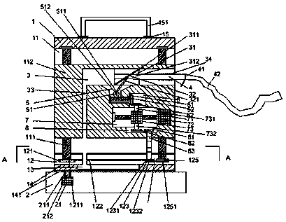
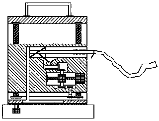
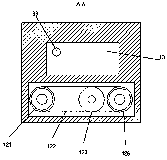
[0016] Such as Figure 1-Figure 4 As shown, a new type of micro-molding injection molding machine of the present invention includes a through-hole seat 2 and a housing 1 fixedly arranged above the through-hole seat 2. It is characterized in that: the housing 1 is provided with a first cavity 11, a second Two smoothing chambers 12 and a sliding table 13, the second smoothing chamber 12 is provided with up and down smoothing equipment, the first cavity 11 is provided with up and down smoothing screw rods 111 on the left and right, and the top of the upper and lower smoothing screw rods 111 is in contact with the housing 1 The inner top wall is connected by rolling fit, the bottom end of the upper and lower smooth screw rods 111 is connected by rolling fit with the inner wall of the housing 1 through the index plate, and the bottom of the upper and lower smooth screw rods 111 is fixedly provided with a first pulley 121 and a second pulley 125 The upper and lower smooth screw rods 11


PUM


Abstract

The invention discloses a micro-molding injection molding machine. The injection molding machine comprises a through hole seat and a housing fixedly arranged above the through hole seat, a first cavity and a second cavity are formed in the housing, up-and-down horizontal sliding equipment is arranged in the second cavity, up-and-down horizontal sliding screw rods are symmetrically arranged on leftand right of the interior of the first cavity, the tops of the up-and-down horizontal sliding screw rods are in rolling cooperative connection with the inner top wall of the housing, the bottoms of the up-and-down horizontal sliding screw rods are in rolling cooperative connection with the inner wall of the housing through indexing discs, up-and-down horizontal sliding compression bodies are in threaded cooperative connection with the up-and-down horizontal sliding screw rods, and assembling and dismantling devices are arranged at the lower end faces of the up-down horizontal sliding compression bodies. The injection molding machine has the advantages of simple structure and convenient operation and is suitable for the production of most of micro plastic products on the market, a user does not need to purchase expensive large equipment, so that the purchasing cost and maintenance cost of the user are reduced, the user can get rid of dilemmas of high operation noise and small operationspace of micro plastic product production, and great convenience is provided for the user.

Description


Claims


Application Information

Patent Timeline
Owner 楼一
Why Eureka
Try Eureka