Microimaging optical system of imaging flow cytometry

A flow cytometer and microscopic imaging technology, applied in the field of optical instruments, can solve the problems of inability to improve the resolution of the cytometer, the imaging quality cannot be achieved, and the number of spectral imaging channels is small.

Inactive Publication Date: 2015-03-25
CHANGCHUN INST OF OPTICS FINE MECHANICS & PHYSICS CHINESE ACAD OF SCI
View PDF10 Cites 4 Cited by
  • Summary
  • Abstract
  • Description
  • Claims
  • Application Information

AI Technical Summary

Problems solved by technology

[0005] In order to solve the problems that the optical system of the existing imaging flow cytometer has fewer spectral imaging channels, the imaging quality cannot reach

Method used


Image

  • Microimaging optical system of imaging flow cytometry
  • Microimaging optical system of imaging flow cytometry
  • Microimaging optical system of imaging flow cytometry

Examples


Embodiment Construction

[0030] The present invention will be described in further detail below in conjunction with the accompanying drawings.

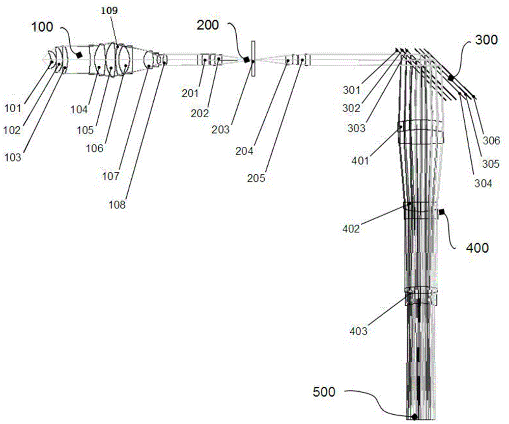
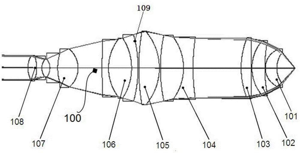
[0031] Such as figure 1 As shown, the microscopic imaging optical system of the imaging flow cytometer of the present invention includes a microscopic objective lens 100 , a secondary imaging lens group 200 , a multispectral spectroscopic device 300 , a multispectral imaging objective lens 400 and a TDI camera 500 . The sample to be tested completes full-band high-resolution magnified imaging through the achromatic microscope objective lens 100, and then passes through the secondary imaging lens group 200 to obtain an intermediate image plane, where a field diaphragm 203 is placed, and then passes through the secondary The imaging lens group 200 is collimated, the light is split by stacking the multi-spectral spectroscopic device 300 , and finally converges to the TDI camera 500 through the multi-spectral imaging objective lens 400 .

[0032] The microscope obj


PUM

PropertyMeasurementUnit
Thicknessaaaaaaaaaa
Surface radius of curvatureaaaaaaaaaa
Thicknessaaaaaaaaaa

Abstract

The invention discloses a microimaging optical system of an imaging flow cytometry and relates to the field of optical instruments applied to biology and medicine. The system solves the problems of an existing optical system of the imaging flow cytometry that the number of spectral imaging channels is small, imaging quality can not reach diffraction limit, and the resolution of the cytometry can not be improved. The system comprises a microobjective, a secondary imaging lens set, a multi-spectral light splitter, a multi-spectral imaging lens and a TDI camera. Full-wave band high-resolution amplification imaging of a sample to be tested is achieved through the achromatic microobjective, then an intermediate image plane is obtained through the secondary imaging lens set, a field stop is placed at the position of the intermediate image plane, collision is conducted through the secondary imaging lens set, stack splitting is conducted through the multi-spectral light splitter, and then light is converged on the TDI camera through the multi-spectral imaging lens. According to the system, full-spectrum subband multiple structures are adopted, it is guaranteed that the imaging quality of the imaging optical system can reach diffraction limit in any spectrum channel, and the minimum detection size of the whole system reaches 40 nm.

Description


Claims


Application Information

Patent Timeline
Owner CHANGCHUN INST OF OPTICS FINE MECHANICS & PHYSICS CHINESE ACAD OF SCI
Why Eureka
Try Eureka