Driving apparatus for electric vehicle

A driving device, electric vehicle technology, applied in the direction of electric vehicle, electric device, electric vehicle charging technology, etc., can solve the problem of difficult charging and so on

Active Publication Date: 2015-05-27
LG MAGNA E POWERTRAIN CO LTD
View PDF5 Cites 1 Cited by
  • Summary
  • Abstract
  • Description
  • Claims
  • Application Information

AI Technical Summary

Benefits of technology

The electrical car driving system uses two types of power sources: one for starting up an engine while another voltage level helps maintain good performance even if there are sudden changes like overheated wires that could affect its ability to start up properly. This allows multiple charged batteries at once to provide more flexibility than just having only one type of source available.

Problems solved by technology

This patents describes how electric car manufactures have been trying to reduce their carbon footprint while maintaining good fuel economy standards through increased emissions control laws. One solution involves adding more lithium ion technology into hybrid electric vehicles - specifically replacing traditional fossil fuels like gasoline and diesel oil with clean sources such as solar cells. Another option would involve developing new types of batterles called zero emission lead acid storage batteries (ZESBs), where they could store electrical charges during operation instead of relying solely upon conventional AC/DC converders.

Method used


Image

  • Driving apparatus for electric vehicle
  • Driving apparatus for electric vehicle
  • Driving apparatus for electric vehicle

Examples


Embodiment Construction

[0045] Hereinafter, an electric vehicle driving device (hereinafter, sometimes referred to as a driving device) according to an embodiment of the present invention will be described in detail with reference to the drawings. The drawings show exemplary aspects of the present invention, and are provided only for explaining the present invention in detail, and do not limit the technical scope of the present invention accordingly.

[0046] In addition, the same reference numerals are attached to the same or corresponding constituent elements regardless of the reference numerals, and repeated description thereof will be omitted. For convenience of description, the size and shape of each constituent member shown may be exaggerated or enlarged. Zoom out.

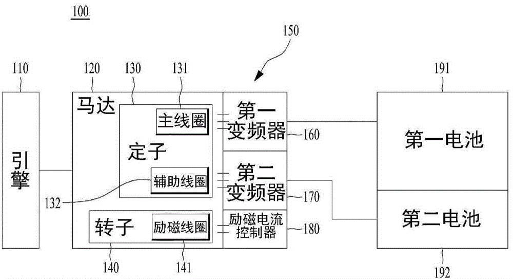
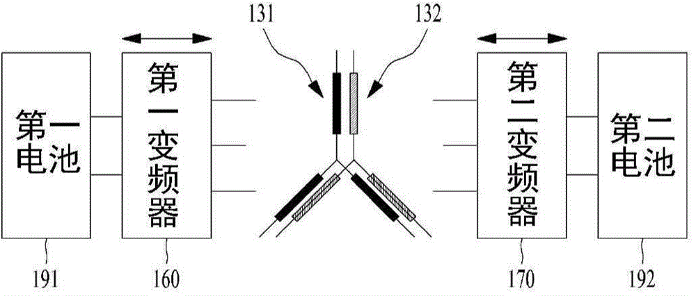
[0047] figure 1 and figure 2 It is a conceptual diagram of an electric vehicle driving device 100 according to an embodiment of the present invention.

[0048] refer to figure 1 , The drive device 100 according to an embodiment o


PUM


Abstract

A driving apparatus for an electric vehicle includes a motor including a stator having a main winding and an auxiliary winding and a rotor rotating due to magnetic interaction between the main winding and the auxiliary winding, an engine configured to selectively rotate the rotor, a motor controller including a first inverter connected to the main winding and a second inverter connected to the auxiliary winding, a first battery connected to the first inverter and configured to drive the motor or configured to be chargeable by the motor, and a second battery connected to the second inverter, configured to be chargeable by the motor, and having a charging voltage lower than that of the first battery.

Description


Claims


Application Information

Patent Timeline
Owner LG MAGNA E POWERTRAIN CO LTD
Why Eureka
Try Eureka