Horizontal casting machine

A casting machine, horizontal technology, applied in casting equipment, equipment for feeding molten metal into molds, metal processing equipment, etc., can solve problems such as damage, laborious formwork, affecting product quality, etc., so that it is not easy to tilt and deviate, and is applicable Wide range and good equipment stability

Inactive Publication Date: 2015-06-03
WUXI SHUANGQUAN MECHANICAL FACTORY
View PDF0 Cites 1 Cited by
  • Summary
  • Abstract
  • Description
  • Claims
  • Application Information

AI Technical Summary

Benefits of technology

This new type of gravure foundry machines was designed with an improved mechanism that allows it to produce very precise cast products without having to move or adjust its position during production. It also includes featuring stable components like rods and guides used to control movement within the machine's main body while still producing accurate results. Overall this innovation improves efficiency and reduces costs compared to traditional methods such as sandwich processes.

Problems solved by technology

This patented technical problem addressed in this patents relates to improving the precision and stability of conventional gravitational casting machines used for producing heavyweight products such as steel pipes or tubular components during their fabrication cycles while also maintaining good guidance and alignment between different parts within these machines' structures without causing excessive strains on them overall.

Method used


Image

  • Horizontal casting machine
  • Horizontal casting machine

Examples


Embodiment Construction

[0012] The present invention will be further described below in conjunction with the accompanying drawings and embodiments.

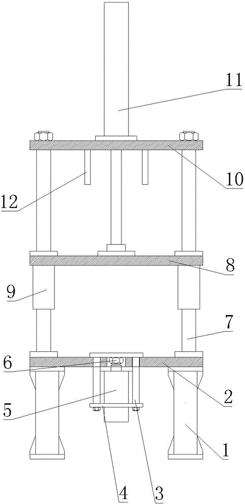
[0013] See figure 1 , figure 2 , the present invention includes a lower fixed formwork 2 installed on a foot 1, the lower end of the lower fixed formwork 2 is connected with a mounting plate 4 through a screw 3, a core-pulling oil cylinder 5 is fixed on the mounting plate 4, and the piston rod of the core-pulling oil cylinder 5 extends upwards The top block 6 is installed on the top of the piston rod, the four corners of the lower fixed template 2 are respectively provided with guide pillars 7, the four corners of the movable template 8 are respectively provided with guide sleeves 9, and the movable template 8 passes through the guide pillars 7 and the guide sleeves. 9 is mounted on the guide post 7 with sliding fit, the top of the guide post 7 is fixedly connected with the upper fixed formwork 10, and the upper fixed formwork 10 is fixed with a lifting


PUM


Abstract

The invention discloses a horizontal casting machine. The horizontal casting machine is characterized in that the structure is simplified so that the casting machine is appropriate for casting large castings, the load of an oil cylinder is reduced, the service life of the oil cylinder is prolonged, the guide precision is high and the casting quality is effectively improved. The horizontal casting machine comprises a lower fixing template installed on stand bars, wherein the lower end of the lower fixing template is connected with an installing plate by screws, a core pulling cylinder is fixed to the installing plate, the piston rod of the core pulling cylinder is extended upward and the top of the piston rod is equipped with a top block, four corners of the lower fixing template are respectively equipped with guide posts, four corners of a moveable template are respectively equipped with guide sleeves, the moveable template in sliding matches with the guide sleeves through the guide posts and is installed on the guide posts, the top of each guide post is fixedly connected with an upper fixing template, the upper fixing template is fixed with a lifting cylinder, and the piston rod of the lifting cylinder is extended downward and fixedly connected with the moveable template.

Description


Claims


Application Information

Patent Timeline
Owner WUXI SHUANGQUAN MECHANICAL FACTORY
Why Eureka
Try Eureka