Mechanism with double degrees of freedom

A degree of freedom, linear motor technology, applied in the direction of electromechanical devices, control mechanical energy, electrical components, etc., can solve the problems of maximum speed limit, difficult to achieve high-speed and high-precision positioning, and achieve high accuracy and acceleration, and compact structure.

Active Publication Date: 2015-07-01
东莞固高自动化技术有限公司
View PDF5 Cites 3 Cited by
  • Summary
  • Abstract
  • Description
  • Claims
  • Application Information

AI Technical Summary

Problems solved by technology

Due to the maximum speed limit and backlash of the intermediate link screw, synchronous

Method used


Image

  • Mechanism with double degrees of freedom
  • Mechanism with double degrees of freedom

Examples


Embodiment Construction

[0024] In order to facilitate the understanding of those skilled in the art, the present invention will be further described below in conjunction with the accompanying drawings.

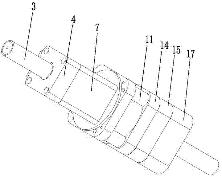
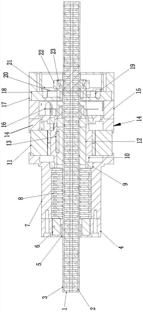
[0025] as attached figure 1 with 2 As shown, the present invention discloses a two-degree-of-freedom mechanism, including a housing 7, which is provided with a linear motor and a direct drive rotary motor, and the linear motor includes a linear motor stator 8 housed in the housing 7 , the linear motor mover 3 and the self-lubricating bearing 5, the linear motor mover 1 passes through the self-lubricating bearing 5 and the linear motor stator 8 and cooperates with the linear motor stator 8 in clearance; the direct drive rotary motor includes a rotary motor stator 11 and The rotor 10 of the rotating electrical machine, the stator 11 of the rotating electrical machine is installed on the casing 7, the rotor 10 of the rotating electrical machine is clamped on the casing 7 and is located between the casing


PUM


Abstract

The invention discloses a mechanism with double degrees of freedom. The mechanism comprises a shell and a band-type brake device. A linear motor and a direct-drive rotary motor are arranged in the shell, the linear motor comprises a linear motor stator, a linear motor rotor and a self-lubricating bearing, the linear motor stator is arranged in the shell, the linear motor rotor penetrates the self-lubricating bearing and the linear motor stator and is in clearance fit with the linear motor stator, the direct-drive rotary motor comprises a rotary motor stator and a rotary motor rotor, the rotary motor stator is arranged on the shell, the rotary motor rotor is clamped on the shell and is positioned between the shell and the rotary motor stator, a rotary bearing is arranged in the shell and is butted to the rotary motor rotor, a spline housing is arranged in the rotary motor rotor, the linear motor rotor penetrates the spline housing, the band-type brake device is arranged on the linear motor rotor, and the linear motor rotor can be locked or released by the band-type brake device. The mechanism has the advantages that intermediate transmission mechanisms can be omitted, the mechanism is provided with the band-type brake device, and accordingly precision and speed control can be effectively improved.

Description


Claims


Application Information

Patent Timeline
Owner 东莞固高自动化技术有限公司
Why Eureka
Try Eureka