Rear suspension device

A rear suspension and cantilever technology, applied in agricultural machinery and implements, applications, agricultural machinery, etc., can solve the problems of poor comfort, difficult maintenance, severe vibration, etc., to achieve stable operation, increase contact area, and avoid stress concentration. Effect

Active Publication Date: 2015-08-26
XINGGUANG AGRI MACHINERY
View PDF9 Cites 0 Cited by
  • Summary
  • Abstract
  • Description
  • Claims
  • Application Information

AI Technical Summary

Problems solved by technology

[0005] In order to solve the shortcomings in the above-mentioned prior art, the present invention proposes a rear suspension device to solve the problems of difficult maintenance, severe vibration, poor comfort, etc.

Method used


Image

  • Rear suspension device
  • Rear suspension device
  • Rear suspension device

Examples


Example Embodiment

[0041] The present invention will be further described in detail below with reference to the accompanying drawings and embodiments. It should be understood that the specific embodiments described herein are only used to explain the present invention, but not to limit the present invention.

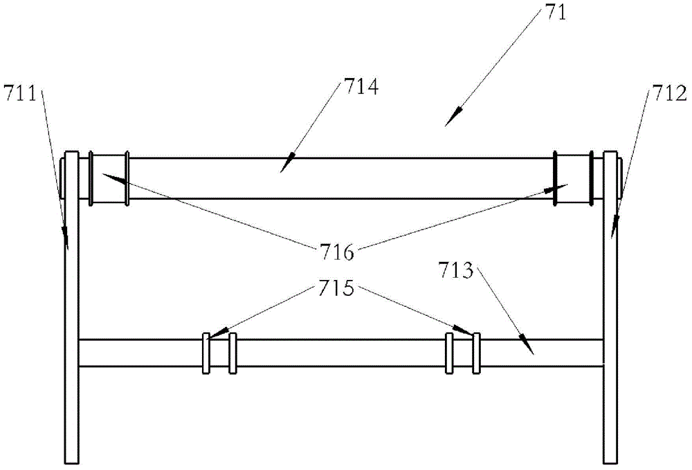
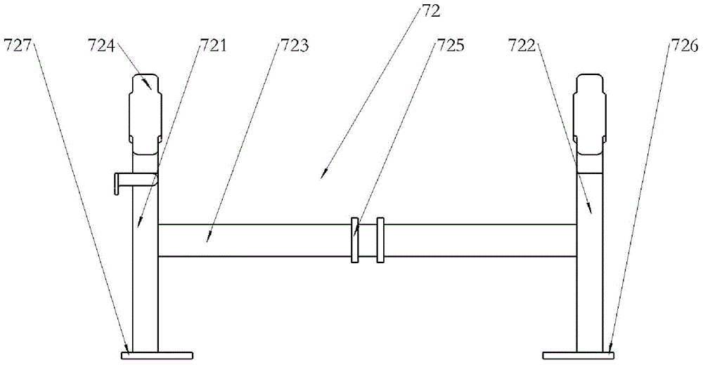
[0042] As shown in the figure, a rear suspension device includes an upper frame 71 and a lower frame 72, the upper frame 71 is connected with the lower frame 72, the upper frame 71 extends backward at its connection with the lower frame 72, and the rear end of the upper frame 71 extends beyond the chassis machine At the rear end of the frame 11, the lower frame 72 includes a left column 721 and a right column 722, the left column 721 and the right column 722 are arranged in parallel, and the bottoms of the left column 721 and the right column 722 have two connecting plates 727, the two connecting plates 727 are respectively fixedly connected to the lower ends of the left pillar 721 and the ri


PUM


Abstract

The invention relates to a rear suspension device. The rear suspension device is detachably mounted on a chassis frame (11), and comprises an upper frame (71) and a lower frame (72), which are connected; the upper frame (71) extends backwards at the joint between the upper frame (71) and the lower frame (72); the rear end of the upper frame (71) is longer than that of the chassis frame (11). The rear suspension device is arranged on the chassis frame, and has the advantages that since the rigidity of the chassis frame is far higher than that of a rear gearbox body, the bonding strength is greatly improved; the width of the chassis frame is larger, and the width of the rear suspension device is increased accordingly, so that a mounted agricultural implement with larger width can be selected, and the farming efficiency is improved greatly; the rear suspension device is detachably connected with the chassis frame, and if the rear suspension device is damaged in farming, the rear suspension device can be quickly detached for replacement.

Description


Claims


Application Information

Patent Timeline
Owner XINGGUANG AGRI MACHINERY
Why Eureka
Try Eureka