Circumferentially rotatable antenna and rotating method thereof

An antenna and circumference technology, applied in the direction of the antenna support/installation device, etc., can solve the problems of the angle and range of the antenna reflector receiving signals being small, the accuracy and efficiency of satellite antenna finding signals, etc. Effect

Inactive Publication Date: 2015-09-30
SVEC ELECTRONICS SUZHOU +1
View PDF6 Cites 0 Cited by
  • Summary
  • Abstract
  • Description
  • Claims
  • Application Information

AI Technical Summary

Benefits of technology

This patented technology allows for better control over directional radiation patterns when transmitting radio waves or receiving electromagnetic waveforms (EW). It uses a special type of reflector called a cylindrical lens made up of multiple layers of metal arranged around another circle-shaped body. By changing the orientation of this layered material within certain specific ranges, it becomes possible to change how much signal energy travels throughout space without affecting their original properties.

Problems solved by technology

This patented technical problem addressed in this patents relates to improving the efficiency with radios' reception capabilities while minimizing interference between different types of waves such as terrestrial radio broadcastings and cellular communication systems.

Method used


Image

  • Circumferentially rotatable antenna and rotating method thereof
  • Circumferentially rotatable antenna and rotating method thereof
  • Circumferentially rotatable antenna and rotating method thereof

Examples


Embodiment Construction

[0027] In order to make the above objects, features and advantages of the present invention more comprehensible, specific implementations of the present invention will be described in detail below in conjunction with the accompanying drawings.

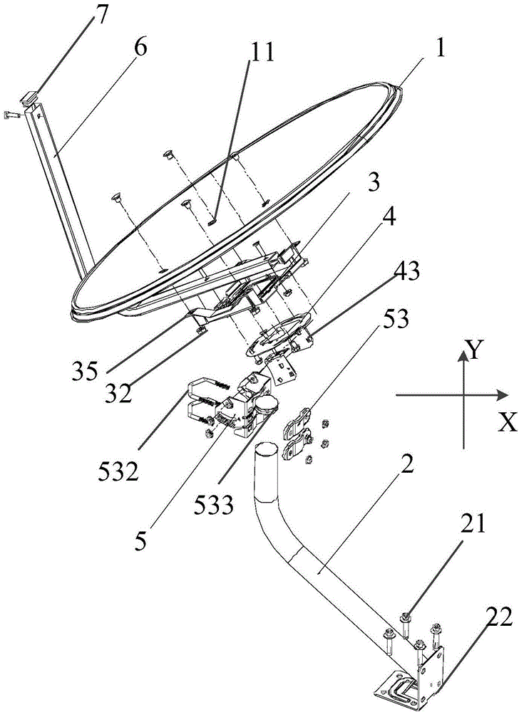
[0028] Please refer to figure 1 , the circularly rotatable antenna provided by the present invention includes an antenna reflective surface 1 and a column 2, the antenna reflective surface 1 is located on the upper part of the column 2, and the column 2 is used to support the antenna reflective surface 1 and fix the position of the antenna reflective surface 1, and the column 2. The bottom is fixed on the wall through the fixing plate 22 and the eighth bolt 21. The fixing plate 22 is connected to the bottom of the column 2. At least four eighth bolts 21 are used to fix the fixing plate 22 on the wall. Generally, a bracket can also be used to support the column 2 on the ground, so that the bracket fixed with the column 2 can be directly pl


PUM


Abstract

The invention provides a circumferentially rotatable antenna. The antenna comprises an antenna reflection surface and a stand column, wherein the antenna reflection surface is round and has a concave surface, a tuner connected at the top end of a feed source rod is arranged on the side of the concave surface of the antenna reflection surface, the stand column for supporting the antenna is arranged on the side of a convex surface of the antenna reflection surface, the antenna reflection surface is sequentially connected with a back clip, an adjusting head and the stand column, and the back clip and the adjusting head are connected with each other through a circumferential rotation structure. The invention further provides a rotating method of the antenna. When the antenna reflection surface is required to rotate circumferentially, the back clip is disconnected from the circumferential rotation structure, and after the antenna reflection surface is rotated circumferentially with the center of the antenna reflection surface serving as the circle center, the back clip is connected and fixed with the circumferential rotation structure again. When the satellite antenna searches signals, adjustable angle parameters are increased, and the signal receiving angle and range of the antenna reflection surface are enlarged.

Description


Claims


Application Information

Patent Timeline
Owner SVEC ELECTRONICS SUZHOU
Why Eureka
Try Eureka