Pile shoe of drainage plate pile driver

A drainage board and pile driver technology, applied in soil protection, construction, infrastructure engineering, etc., can solve the problems of reducing belt-back rate, high belt-back rate, and low work efficiency, so as to reduce belt-back rate and prevent belt-back Awards, the effect of improving work efficiency

Active Publication Date: 2015-12-02
QINGDAO PORT INT
View PDF7 Cites 0 Cited by
  • Summary
  • Abstract
  • Description
  • Claims
  • Application Information

AI Technical Summary

Benefits of technology

This patented device has several technical advantages over existing devices used alone. These improvements include increased stability when drilling into soft ground without damaging equipment (such as cranes), reduced backflow rates caused by sandy conditions while maintaining effective removal of water after excavation operations, better control over the depths where the dirt will remain, easier maintenance procedures, enhanced safety features such as automatic shutdown mechanisms, and more efficient use of energy resources compared to traditional methods like hydraulic power tools.

Problems solved by technology

This technical problem addressed by this patented method relates to improving the performance of draining systems such as concrete flooding basements during construction without adding extra materials like waterproof seals (SBS) between different parts of the system's pipes. Existing methods involve inserting an excessive amount of adhesives into each part separately after installation, which can lead to waste issues due to incorrect placement of these components.

Method used


Image

  • Pile shoe of drainage plate pile driver
  • Pile shoe of drainage plate pile driver
  • Pile shoe of drainage plate pile driver

Examples


Embodiment Construction

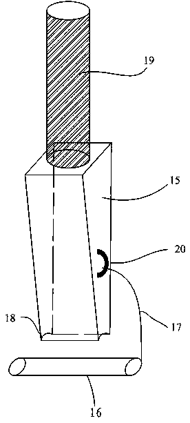
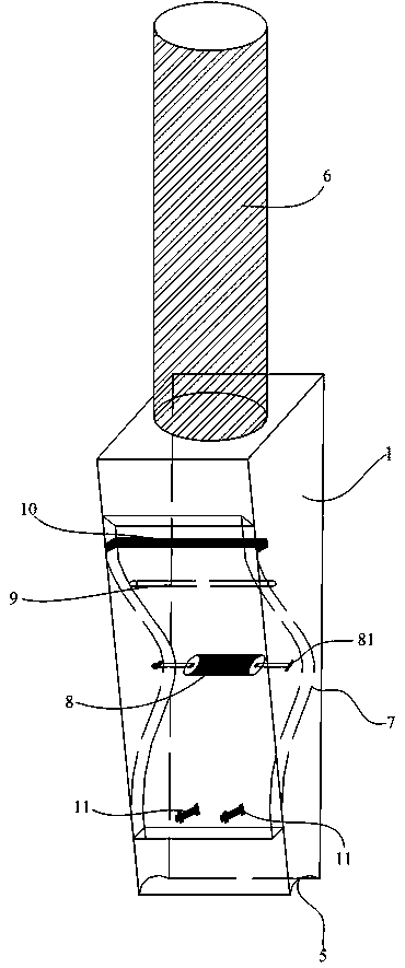
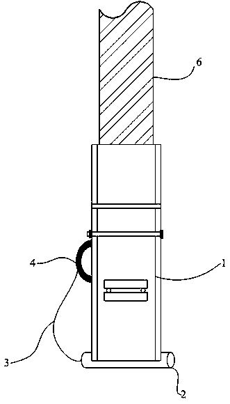
[0021] see Figure 2-Figure 5 , an embodiment of the nozzle of a drainage board pile driver according to the present invention, comprising a nozzle housing 1, a fixing pin 2 and a connecting chain 3, one side of the nozzle housing 1 is provided with a fixing part 4, and the nozzle The bottom end of the housing 1 is provided with a spout 5, the fixed pin 2 is clamped in the spout 5, one end of the connecting chain 3 is connected with the fixing piece 4, and the other end is fixed with the fixed pin 2 connection, the upper end of the pile nozzle housing 1 is fixedly connected with the pile pipe 6, and also includes a drain plate anti-retraction assembly, and the drainage plate anti-retraction assembly includes an arc-shaped elastic plate 7, an eccentric shaft 8 and a pressing member 9 , the inner wall of the pile nozzle housing 1 is provided with an insertion slot 10, the arc-shaped elastic plate 7 passes through the insertion slot 10 and its upper end is clamped in the insertion s


PUM

PropertyMeasurementUnit
Diameteraaaaaaaaaa
Thicknessaaaaaaaaaa

Abstract

The invention provides a pile shoe of a drainage plate pile driver. The pile shoe comprises a pile shoe shell, a fixing pin and a connecting chain. A fixing part is arranged on one side of the pile shoe shell. The fixing pin is clamped in a shoe slot. One end of the connecting chain is connected with the fixing part, and the other end of the connecting chain is fixed to the fixing pin. The upper end of the pile shoe shell is fixed to a pile pipe. A drainage plate back-drawing preventing assembly comprises an arc elastic plate, an eccentric shaft and a compression part. The inner wall of the pile shoe shell is provided with a penetrating slot. The arc elastic plate penetrates through the penetrating slot, the upper end of the arc elastic plate is clamped into the penetrating slot, and the lower end of the arc elastic plate is fixed to the inner wall of the pile shoe shell through a fastener. The compression part compresses the upper end of the arc elastic plate, and the two ends of the compression part are fixed to the inner wall of the pile shoe shell. The eccentric shaft abuts against the inner side of the arc elastic plate, and the two ends of the eccentric shaft are rotationally connected with the pile shoe shell. A plate penetrating groove is formed between the outer side of the arc elastic plate and the inner wall, opposite to the outer side of the arc elastic plate, of the pile shoe shell. By means of the pile shoe, the back-drawing rate is effectively reduced, and working efficiency is improved.

Description


Claims


Application Information

Patent Timeline
Owner QINGDAO PORT INT
Why Eureka
Try Eureka