Waterway control valve unit

A technology for waterway control valves and components, applied in the direction of lift valves, valve details, diaphragm valves, etc., can solve the problems of unsuitable solenoid valves, poor applicability, and easy damage of valve diaphragms, so as to avoid water hammer vibration and improve pressure resistance Ability, the effect of not being easily displaced

Active Publication Date: 2015-12-02
QUANZHOU ZONGNENG ELECTROMAGNETIC VALVE CO LTD
View PDF6 Cites 4 Cited by
  • Summary
  • Abstract
  • Description
  • Claims
  • Application Information

AI Technical Summary

Problems solved by technology

[0003] But in this invention application, there is following defect in the setting of valve mold: (1) although its water outlet is provided with some ribs and protects valve diaphragm, can not provide enough protection, and valve diaphragm has been extruded water inlet and outlet risk, and it will collide with the water outlet, which is easy to be damaged; (2) the invention application cannot completely eliminate the occurrence of water hammer, although there will be no water hammer betw

Method used


Image

  • Waterway control valve unit
  • Waterway control valve unit
  • Waterway control valve unit

Examples


Embodiment Construction

[0038] In order to further explain the technical solution of the present invention, the present invention will be described in detail below through specific examples.

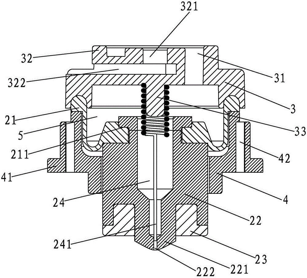
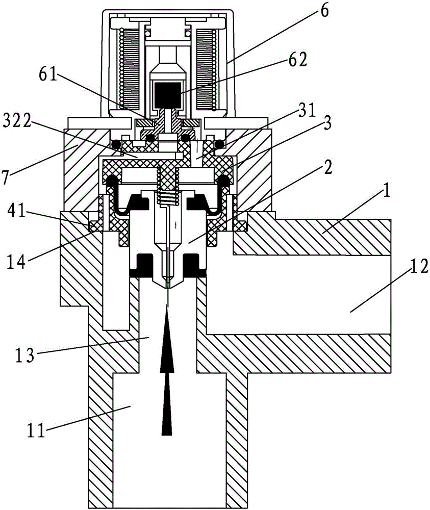
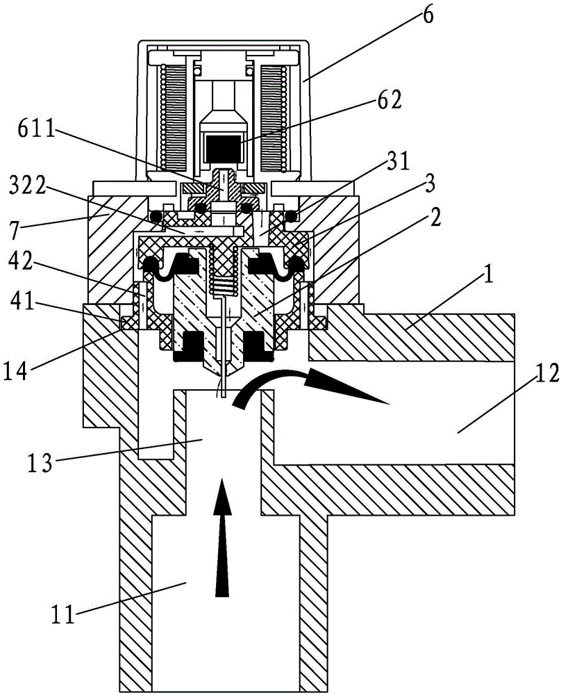
[0039] A waterway control valve assembly, such as Figure 1-Figure 2 As shown, it includes a valve body 1 with a water inlet 11 and a water outlet 12, a valve core set 2 installed in the valve body 1, a diaphragm gland 3 and a shaft sleeve 4, and a valve body is formed between the water inlet 11 and the water outlet 12. Through the hole 13, the diaphragm gland 3 is installed above the spool set 2, and the spool set 2 is arranged above the through hole 13.

[0040] The spool kit 2 is composed of a rubber diaphragm 21, a spool body 22 and a water-stop rubber pad 23 from top to bottom. The spool body 22 is provided with a water inlet channel 24, and the lower part of the spool body 22 has a convex post 221. A balance hole 222 is defined at the lower end of the boss 221 , one end of the balance hole 222 communicates


PUM


Abstract

The invention discloses a waterway control valve unit, comprising a valve element suite, a diaphragm gland, and a shaft sleeve. The diaphragm gland is arranged on the valve element suite. The valve element suite is formed by a rubber diaphragm, a valve element main body, and a watertight rubber pad from top to bottom. The valve element main body is internally provided with a water inlet duct. The lower end of the valve element main body is provided with the watertight rubber pad in a clamping manner. The upper end of the valve element main body is provided with the rubber diaphragm in a clamping manner. A hydraulic pressure balance chamber is formed between the rubber diaphragm and the diaphragm gland. The diaphragm gland is internally provided with a diversion hole communicated with the hydraulic pressure balance chamber. The diaphragm gland is internally provided with a discharge hole which is isolated from the diversion hole. The diaphragm gland is internally provided with a decompression flow channel along the radial direction of the diaphragm gland. The shaft sleeve is sleeved on the rubber diaphragm. A flowing hole is arranged in the shaft sleeve. The waterway control valve unit also comprises a valve body used to install the valve element suite. After the waterway control valve unit is installed with a corresponding waterway control mechanism in a cooperative manner, water hammer vibration can be prevented, and pressure resistance is good, and service life of a product is long.

Description


Claims


Application Information

Patent Timeline
Owner QUANZHOU ZONGNENG ELECTROMAGNETIC VALVE CO LTD
Why Eureka
Try Eureka