Multi-focus array light spot generation device and method

A multi-focus, array technology, applied in the direction of optics, optical components, instruments, etc., can solve the problems of non-adjustable spatial position, lack of flexibility of phase, lack of flexibility, etc.

Active Publication Date: 2015-12-23
LUDONG UNIVERSITY
View PDF3 Cites 15 Cited by
  • Summary
  • Abstract
  • Description
  • Claims
  • Application Information

AI Technical Summary

Problems solved by technology

However, most modulation phases are mainly obtained based on iterative optimization algorithms. The phases obtained based on optimization algorithms lack flexibility, and it is difficult to modulate and control the polarization direction of each focal point in a multi-focus array.
On the other hand, although the polarization direction control of the focal point on multiple diffraction orders can be realized through the interference superposition of two orthogonal light field components [

Method used


Image

  • Multi-focus array light spot generation device and method
  • Multi-focus array light spot generation device and method
  • Multi-focus array light spot generation device and method

Examples


Embodiment 2

[0112] In the following, the incident light wavelength λ=532nm, the numerical aperture of the objective lens NA=1.32, and the refractive index n of the oil-immersed substance t =1.518, and the entrance pupil radius R=3mm is taken as an example to design a specific implementation scheme of multi-focus array spot with adjustable polarization direction and spatial position.

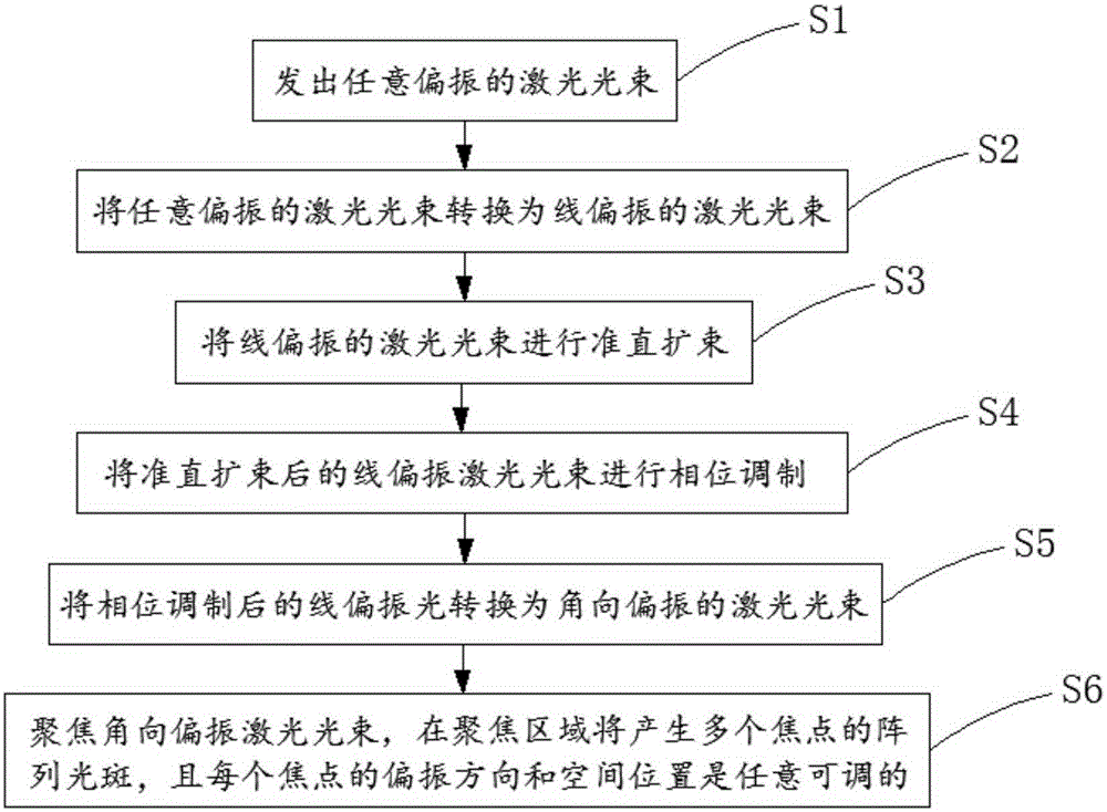
[0113] First, the pure phase modulation on the rear focal plane of the objective lens is designed, and its specific generation method mainly includes the following steps:

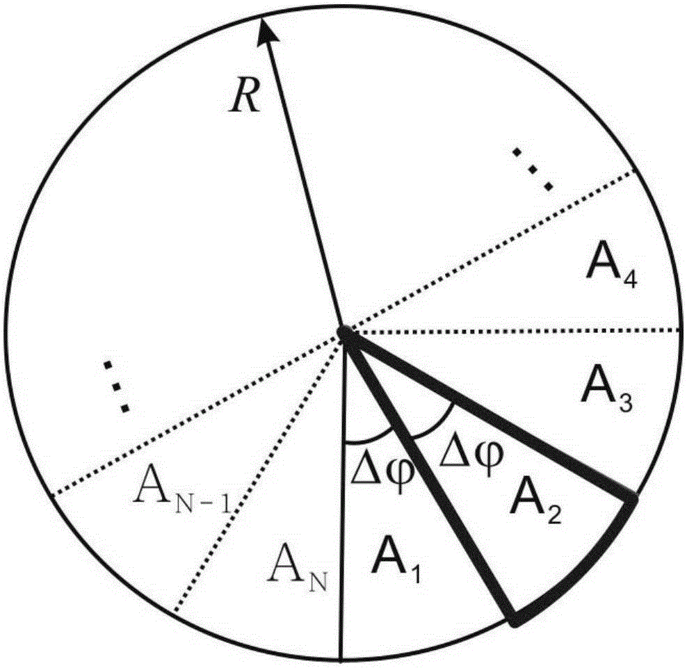
[0114] Step 41: If image 3 As shown, the entrance pupil corresponding to the back focal plane of the objective lens is equally divided into N sectors with the same area: A 1 、A 2 ...A N-1 、A N , where the vertex of each sector is the center of the entrance pupil, the radius of the sector is the radius R of the entrance pupil, and the central angle of each sector is Wherein N is an even number, selects N=72 in the present embodiment;


PUM


Abstract

The invention relates to a multi-focus array light spot generation device and method. The method comprises the following steps: S1) sending an arbitrarily-polarized laser beam; S2) converting the arbitrarily-polarized laser beam into a linearly-polarized laser beam; S3) carrying out collimation and beam expanding on the linearly-polarized laser beam; S4) carrying out phase modulation on the linearly-polarized laser beam obtained after collimation and beam expanding; S5) converting the linearly-polarized laser beam obtained after phase modulation into an azimuthally-polarized laser beam; and S6) focusing the azimuthally-polarized laser beam, and generating multi-focus array light spots in a focusing area, polarization direction and spatial position of each focus being arbitrarily adjustable. Compared with the prior art, the device and method can realize simultaneous adjustment of polarization direction and spatial position of each focus.

Description


Claims


Application Information

Patent Timeline
Owner LUDONG UNIVERSITY
Why Eureka
Try Eureka