Transmission circuit and communication apparatus using polar modulation method
a technology of polar modulation and transmission circuit, applied in the field of transmission circuit, can solve the problems of deterioration of adjacent channel interference characteristics and decrease of achieve the effect of improving the power efficiency of the entire circui
- Summary
- Abstract
- Description
- Claims
- Application Information
AI Technical Summary
Benefits of technology
Problems solved by technology
Method used
Image

Examples
first embodiment
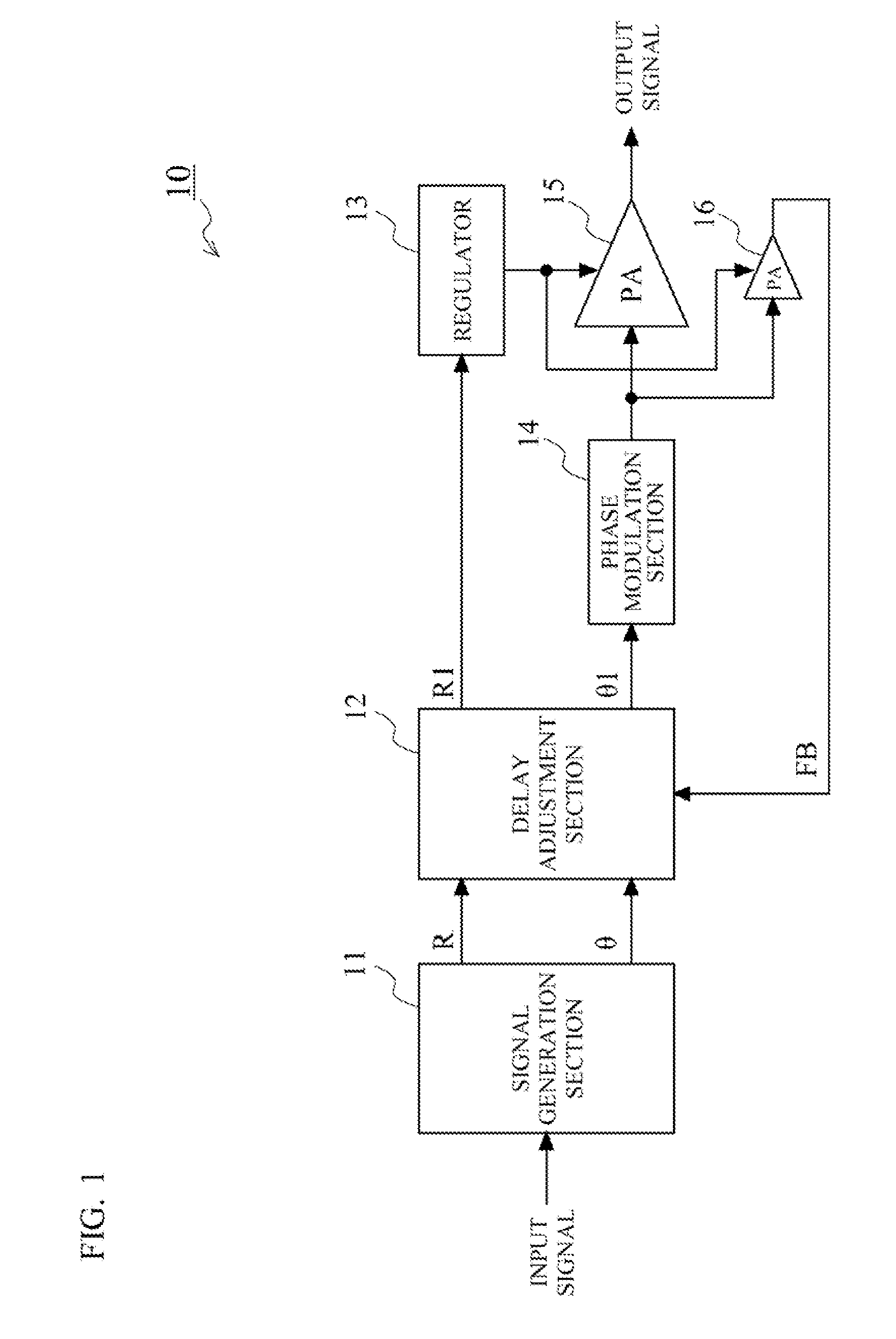
[0032]FIG. 1 shows a configuration of a transmission circuit 10 according to a first embodiment of the present invention. In FIG. 1, the transmission circuit 10 of the first embodiment includes a signal generation section 11, a delay adjustment section 12, a regulator 13, a phase modulation section 14, an amplitude modulation section 15, and a feedback signal generation section 16.
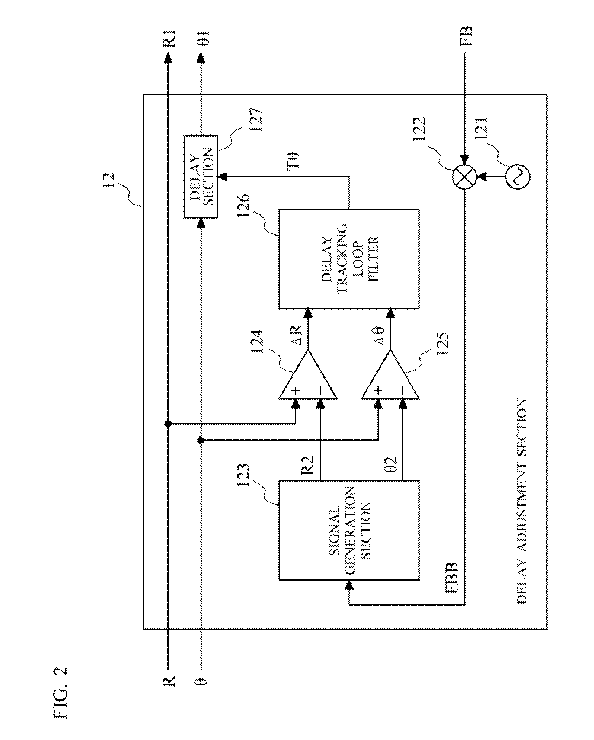
[0033]The signal generation section 11 processes an input signal and thereby generates an amplitude signal R representing an amplitude component and a phase signal θ representing a phase component. The delay adjustment section 12 calculates a difference between a signal delay amount in the amplitude path and a signal delay amount in the phase path based on the amplitude signal R and the phase signal θ generated by the signal generation section 11, and a feedback signal FB outputted from the feedback signal generation section 16. Then, the delay adjustment section 12 adjusts one of or both of an output timing
second embodiment
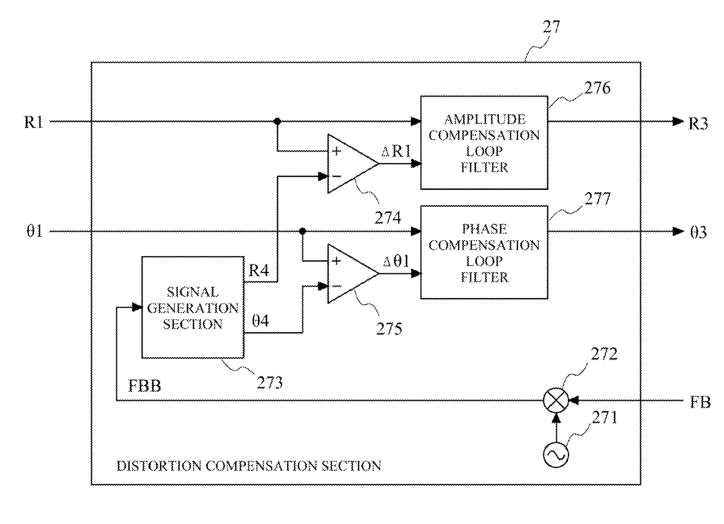
[0049]In a second embodiment, description will be made on a transmission circuit which has an additional function of compensating nonlinear distortion of the amplitude modulation section 15 by making use of a feedback signal FB which includes not only amplitude information but also phase information.
[0050]FIG. 3 shows a configuration of the transmission circuit 20 according to the second embodiment of the present invention. In FIG. 3, the transmission circuit 20 of the second embodiment includes the signal generation section 11, the delay adjustment section 12, the regulator 13, the phase modulation section 14, the amplitude modulation section 15, the feedback signal generation section 16, and a distortion compensation section 27. As shown in FIG. 3, the transmission circuit 20 according to the second embodiment has the same configuration as that of the transmission circuit 10 according to the first embodiment except that the distortion compensation section 27 is added. In the followin
PUM
 Abstract
Description
Claims
Application Information
 - R&D Engineer
- R&D Manager
- IP Professional
- Industry Leading Data Capabilities
- Powerful AI technology
- Patent DNA Extraction
Browse by: Latest US Patents, China's latest patents, Technical Efficacy Thesaurus, Application Domain, Technology Topic.
© 2024 PatSnap. All rights reserved.Legal|Privacy policy|Modern Slavery Act Transparency Statement|Sitemap