Oil and water separation method and oil and water separator

A technology of oil-water separation and oil-water separator, which is applied in separation methods, filtration separation, liquid separation, etc., and can solve problems such as costing a lot of manpower and material resources and consuming huge energy

Active Publication Date: 2016-01-27
邵波
View PDF6 Cites 5 Cited by
  • Summary
  • Abstract
  • Description
  • Claims
  • Application Information

AI Technical Summary

Problems solved by technology

The larger the oil layer, the more favorable the difference in density between oil and water to promote the oil layer to float up under the combined force of gravity and buoyancy to achieve the purpose of oil-water separation, so it is called no matter what type of electric demulsification, no matter what type of chemical demulsification. Milk, or other types of demulsification methods, the final process of oil-water separation is still attributed to the gravity field in which nature endows oil droplets and water droplets with the difference of the resultant force of gravity and buoyancy respectively to separate oil and water, but people mistakenly It is determined that the key to oil-water separation is demulsification, and a lot of manpower, material and financial resources have been spent on how to demulsify, so that the result of the current oil-water separation is to apply a large amount of chemical demulsifiers and consume huge energy and money to demulsify. obtained, but not how to use the free gravity of the earth to "forcefully" pull out the oil droplets from the water body to realize the mechanism of self-separation of oil and water

Method used


Image

  • Oil and water separation method and oil and water separator
  • Oil and water separation method and oil and water separator
  • Oil and water separation method and oil and water separator

Examples


Embodiment Construction

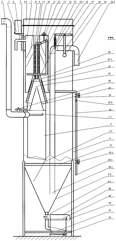
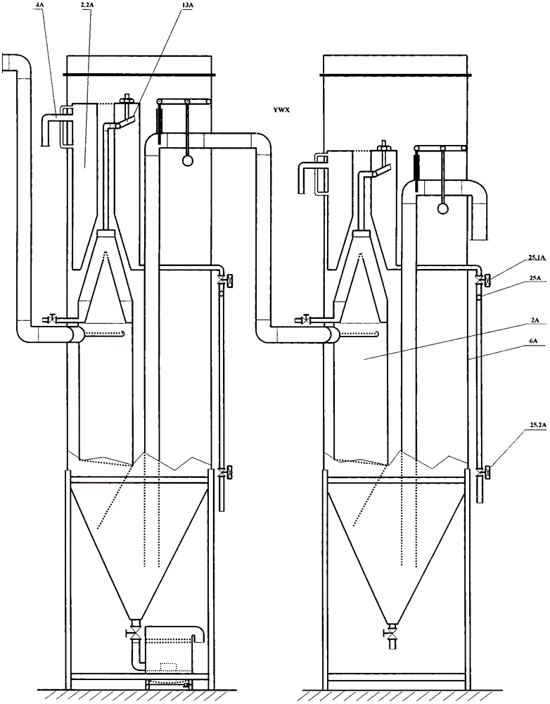
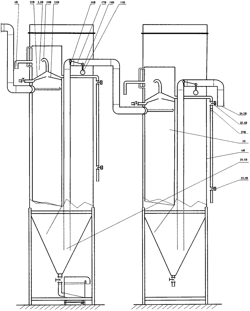
[0051] In order to realize the purpose of the present invention, the present invention has taken the following specific measures.

[0052] Measure 1, the vertical oil-water separation chamber is preferred, so that the vertically downward earth's gravitational force acting on the oil droplets and water droplets will appear without component force at all times.

[0053] The second measure is to determine the sufficient height of the oil-water separation chamber to ensure the multiples of the mechanical effect produced under the condition that the action time of oil-water separation, the separation stroke and the force of the water drops remain unchanged.

[0054] The third measure is to set a special-shaped U-shaped tube with an appropriate cross-sectional area ratio.

[0055] Measure 4: Set up the flow channel of the special-shaped U-shaped pipe to ensure that the oil with low density enters the branch pipe with a small cross-sectional area, and the water body with a high densi...


PUM


Abstract

The invention relates to the industrial and agricultural production and environmental protection fields. Oil droplets and water in a mixed original liquid are forced to move in opposite directions, and the purposes are achieved ingeniously that the force is unchanged and the mechanical motion effects are amplified for n times, just like the oil droplets and water are separated by a force amplified for n times, the separated free water can be forced to be discharged automatically at the water deep where oil droplets cannot reach, and oil and water separation is achieved without a demulsification technology. In addition, free water can be forced to stay in an adjusting water tank with a very low water level for discharge and the oil liquid is discharged at a high oil level far higher than the water level of the adjusting water tank automatically. A heater is arranged in the only path of the oil liquid to guarantee the mobility of the oil liquid. The heater only heats oil and does not heat water, high efficiency and low consumption are achieved, and high-precision oil and water separation of highly thickened oil, crude oil with a density of more than 1 and aged oil can be achieved in a low temperature in a high-efficiency and low-consumption manner. The oil and water separator can be used in a reversed manner, and can become a high-efficiency and low-consumption de-oiling machine, and high-purity oil-free pure water can be obtained. The advanced degree of the method is far better than that of the present oil and water separation technology and great market return can be obtained.

Description

technical field [0001] The oil-water separation method and oil-water separator relate to an oil-water separation method suitable for environmental protection engineering and industrial and agricultural production fields and an oil-water separator whose final main product is dehydrated oil, which is called a dehydrator for short, and the final main product is oil-free pure water. The oil-water separator is referred to as the deoiler for short. Specifically, it is a kind of force that uses the gravitational force of the earth to act on the water droplets and oil droplets in the oil-water mixed stock solution, and skillfully keeps the force and mechanical movement effect of the oil droplets unchanged. And keeping the force of the water droplet constant and amplifying the mechanical movement effect of the water droplet by n times, the water droplet and the oil droplet can be "strongly" pulled apart under the condition that the force of the water droplet and the oil droplet is const...

Claims


Application Information

Patent Timeline
IPC IPC(8): B01D17/025B01D17/06B01D36/04
Inventor 邵波
Owner 邵波
Why Eureka
Try Eureka